Check patentability & draft patents in minutes with Patsnap Eureka AI!

Method of assembling a transducer assembly

a transducer and assembly technology, applied in the direction of electrically conductive connections, electronic products manufacture, printed circuit aspects, etc., can solve the problems of fluxless soldering, difficult automation, and large amount of heating, and achieve faster, more reproducible, and safer.

Active Publication Date: 2016-07-26
SONION NEDERLAND
View PDF100 Cites 3 Cited by
  • Summary
  • Abstract
  • Description
  • Claims
  • Application Information

AI Technical Summary

Benefits of technology

The invention aims to improve the connection between a transducer and a conductor element by making it faster, safer, and more reliable.

Problems solved by technology

The set-up of a) has the disadvantages that it is difficult to automate and that rather large solder bumps or soldering pads are required, thus requiring a large amount of heating.
Especially in lead-free systems, flux-less soldering is problematic, whereby it is preferred to add some flux, solder paste or flux-core solder.
Since the flex is preferably rather thick compared to the hole-size (relatively deep hole), it is difficult to dispense the flux correctly.
Checking visually after dispensing is also difficult, as the flex is positioned over the solder bumps.
This check is, however, desired, as flux is not allowed to enter on to the surface between the solder bumps 3, as this brings about a risk of short-circuit and corrosion.
This heating may bring about a number of problems, such as damage to the transducer, melting and short circuiting of the solder bumps 3, damage to the flex print, etc.
Furthermore, there is a considerable risk of partial melting and bad wetting due to inhomogeneous heat transfer, bringing about an insufficient solder connection quality.
A further complication is that, during soldering, the flex should be kept in the desired position, but a pressed-down flex mounted on this type of solder bumps will usually slant or bend as all solder bumps are not melted simultaneously, but consecutively due to the process of applying heat.
Thus, visual inspection is made quite difficult, whereby there is a considerable risk that a low wetting quality is not spotted, and that short circuits between bumps 3 and flux residues between bumps 3 goes unnoticed (unused flux is etching and causes corrosion risks in the field and burned flux causes a risk for brittle solder connections).

Method used


Image

  • Method of assembling a transducer assembly
  • Method of assembling a transducer assembly
  • Method of assembling a transducer assembly

Examples


Embodiment Construction

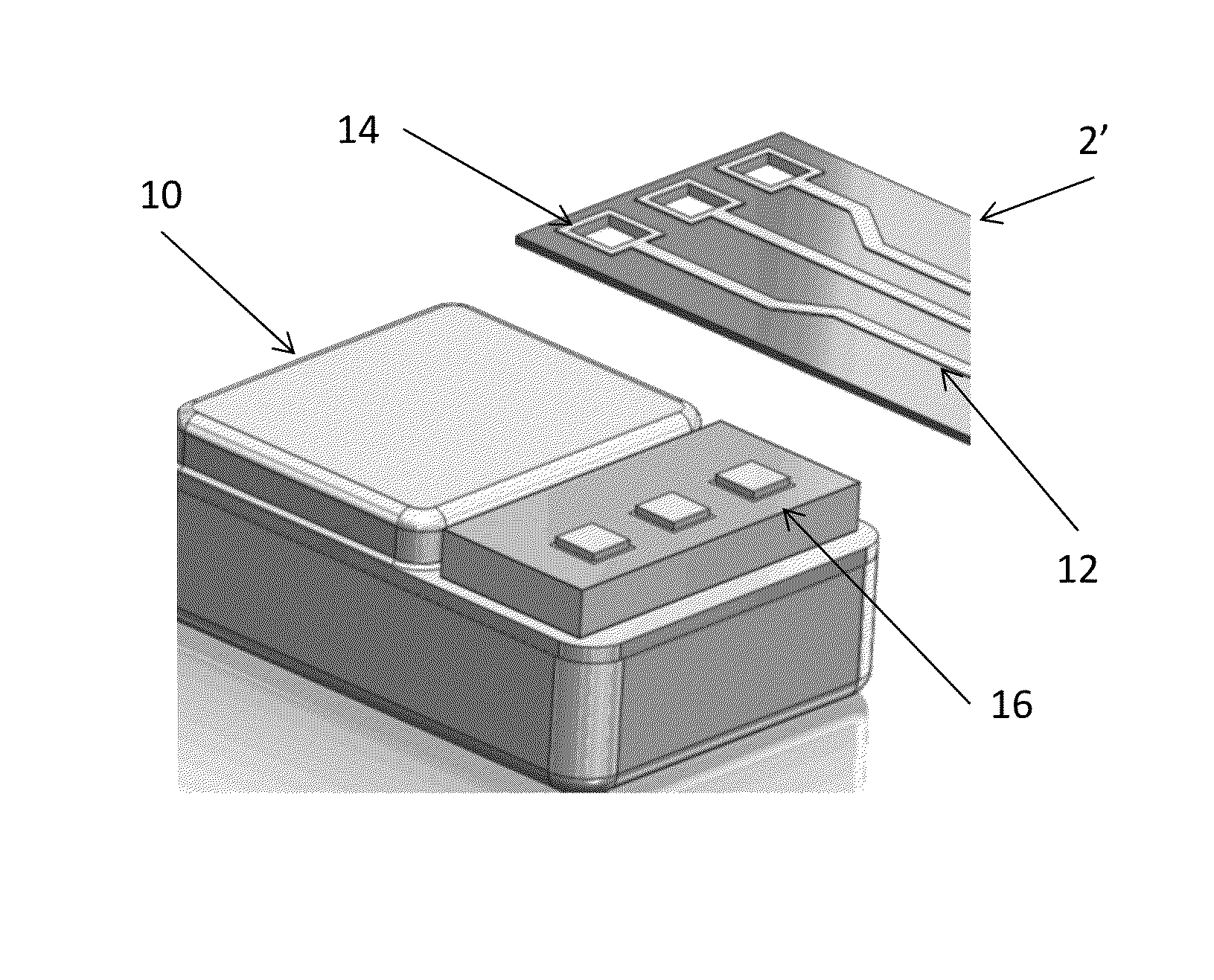
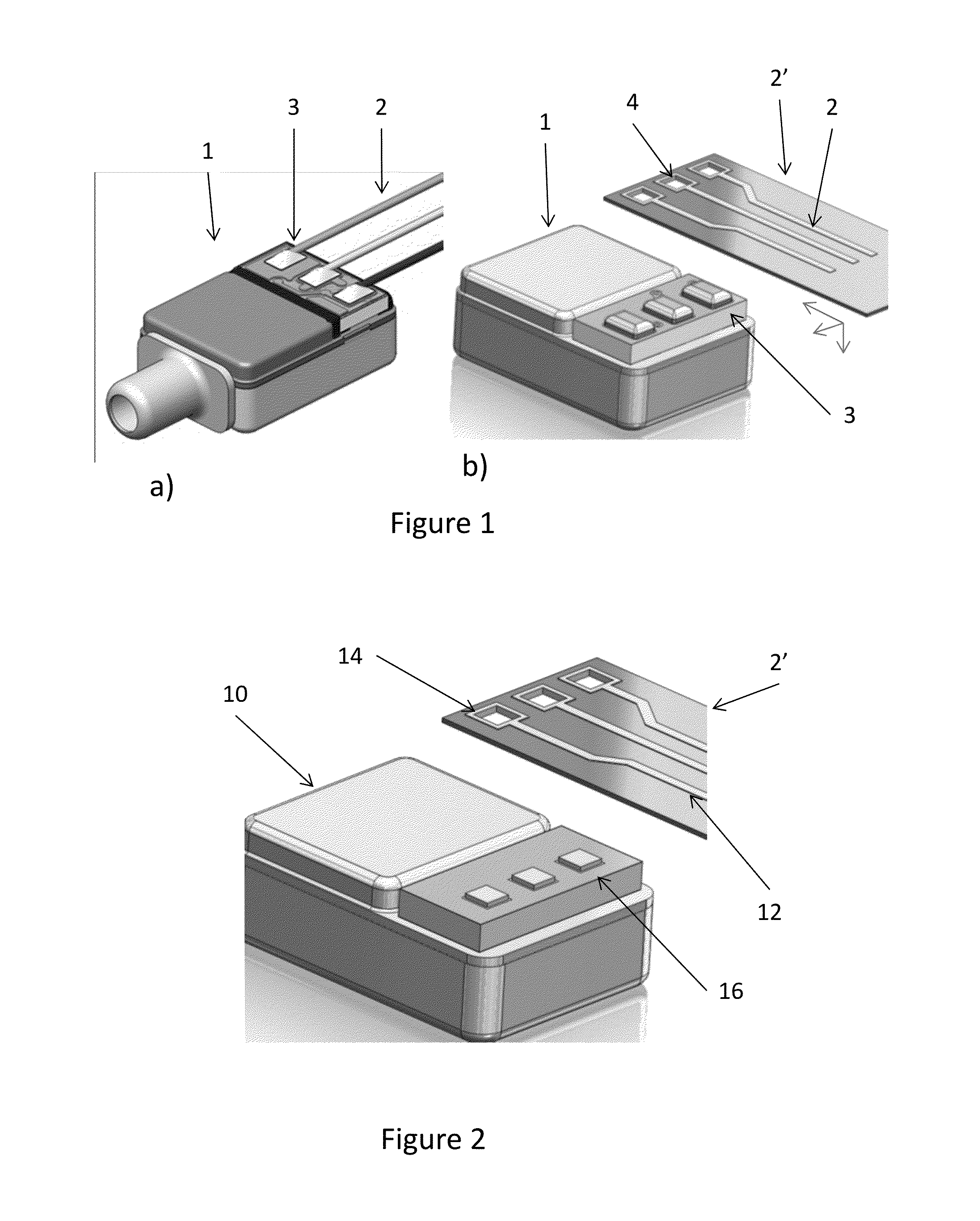
[0092]FIG. 2 illustrates an assembly, before assembly, suitable for the method of the invention, where the transducer 10 has solder bumps or solid bumps 16 and the connector, in this situation also a flex print 2′, has conductors 12 each surrounding a hole 14.

[0093]The difference from FIG. 1b) is that in FIG. 2, the bumps 16 fit inside the openings 14, so that a swift and secure register may be obtained between the bumps 16 and the openings 14.

[0094]Thus, the method may simply be positioning the bumps 16 in the holes 14. This may be a press-fit or a click fit. Alternatively, the bumps 16 may be smaller in area than the holes 14. The result is a swift register (also called “Auto-aligning”) which may even be acknowledged or sensed by a click or the like.

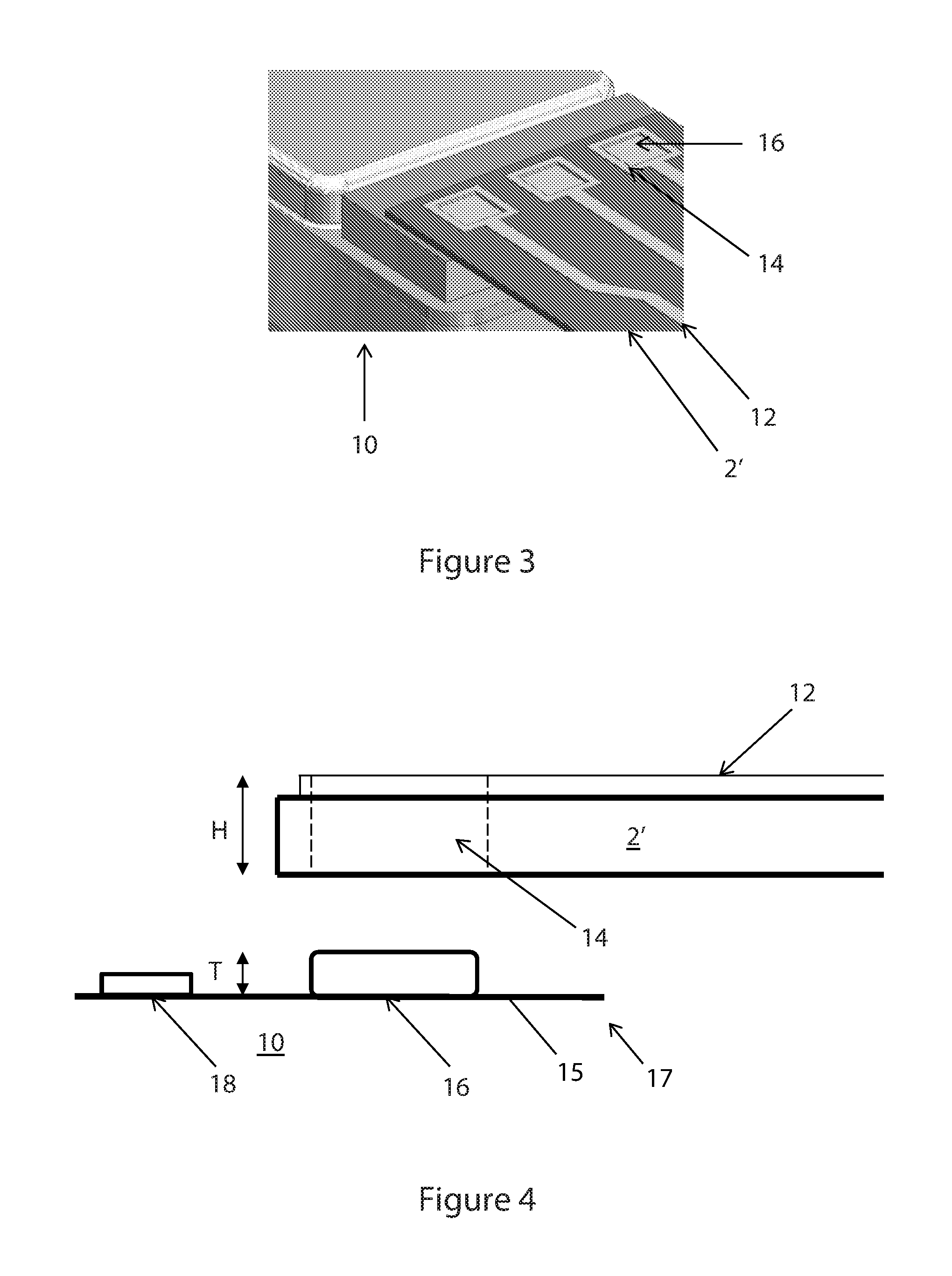
[0095]It is noted that in this set-up, pressure is only required along one direction to keep the alignment / register before and during soldering / fastening.

[0096]It is preferred that the bumps 16 are made slightly lower than the flex-thi...


PUM

PropertyMeasurementUnit
distanceaaaaaaaaaa
distanceaaaaaaaaaa
distanceaaaaaaaaaa

Abstract

A method of assembling a transducer assembly comprising a transducer and a conductor element, where one of the transducer and the conductor element includes holes and conducting parts, each conducting part being exposed in or at a hole and the other of the transducer and the conductor element includes elevated, electrically conducting elements. The method includes aligning the conductor element and the transducer so that each of the elevated elements extends into a separate hole of the holes and fixing the transducer to the conductor element by fixing each elevated element to the conducting parts of the pertaining hole.

Description

CROSS-REFERENCE TO RELATED APPLICATION[0001]This application claims the benefit of Danish Patent Application Serial No. PA201370292, filed May 29, 2013, and titled “A Method of Assembling a Transducer Assembly,” which is incorporated herein by reference in its entirety.FIELD OF THE INVENTION[0002]The present invention relates to a method of assembling a transducer assembly and in particular a manner of obtaining swift and reproducible interconnection between a transducer and a conductor element.BACKGROUND OF THE INVENTION[0003]In FIG. 1, prior art assemblies are illustrated where electrical connection to a transducer 1 is made using, in a), three wires 2 each soldered to solder bumps 3 of the transducer.[0004]The set-up of a) has the disadvantages that it is difficult to automate and that rather large solder bumps or soldering pads are required, thus requiring a large amount of heating.[0005]In b), the conductors 2 form part of a flex print 2′ having openings 4 each surrounded by a ...

Claims


Application Information

Patent Timeline
Patent Type & Authority Patents(United States)
IPC IPC(8): H01R4/02H05K3/34H05K1/11H01R43/00H05K3/30H05K3/32H05K1/18
CPCH01R43/00H01R4/027H01R4/028H05K1/118H05K3/3436H05K1/189H05K3/303H05K3/325H05K2201/094H05K2201/0969H05K2201/09854H05K2201/10083H05K2203/167H05K2203/168Y02P70/613Y10T29/49005Y02P70/50
Inventor BOSCH, JOZEF JOHANNES GERARDUS
Owner SONION NEDERLAND
Features
  • R&D
  • Intellectual Property
  • Life Sciences
  • Materials
  • Tech Scout
  • Unparalleled Data Quality
  • Higher Quality Content
  • 60% Fewer Hallucinations
Learn More