Actuator

a technology of actuators and actuators, applied in the field of actuators, can solve the problems of increasing the weight of the actuator, the structure of the actuator becoming more complicated, and the size of the actuator to become larger, so as to reduce the structure of the actuator can be made simpler and smaller, and the increase in the weight of the actuator can be suppressed.

Active Publication Date: 2016-08-02
NABLESCO CORP
View PDF16 Cites 2 Cited by
  • Summary
  • Abstract
  • Description
  • Claims
  • Application Information

AI Technical Summary

Benefits of technology

[0009]With such an actuator as one disclosed in U.S. Pat. No. 5,111,708 or the above NASA literature, the driving force conversion mechanism needs the rotation restriction mechanism for restricting rotation of the linearly displaced element, which is one of the nut portion and the screw portion. This rotation restriction mechanism, which is built as a structure capable of restricting the rotation of one of the nut portion and the screw portion, would cause the actuator to become larger, and cause the structure thereof to become more complicated. Moreover, a larger actuator would result in increase in the weight thereof. Furthermore, a larger actuator would also result in more constraints on the installation space for the actuator. Consequently, an actuator whose rotation restriction mechanism can be made simpler and smaller and whose installation space can be made more compact is desired.
[0010]In light of the foregoing situation, it is an object of the present invention to provide an actuator whose mechanism for restricting rotation of a linearly displaced element that is one of the nut portion and the screw portion can be made simpler and smaller, whose structure can be made simpler and smaller, and whose installation space can be made more compact.

Problems solved by technology

This rotation restriction mechanism, which is built as a structure capable of restricting the rotation of one of the nut portion and the screw portion, would cause the actuator to become larger, and cause the structure thereof to become more complicated.
Moreover, a larger actuator would result in increase in the weight thereof.
Furthermore, a larger actuator would also result in more constraints on the installation space for the actuator.
Therefore, rotational displacement of the piston around its axis is restricted, and rotation of the piston around the axis of the nut portion and the screw portion is also restricted.

Method used


Image

  • Actuator
  • Actuator
  • Actuator

Examples


Embodiment Construction

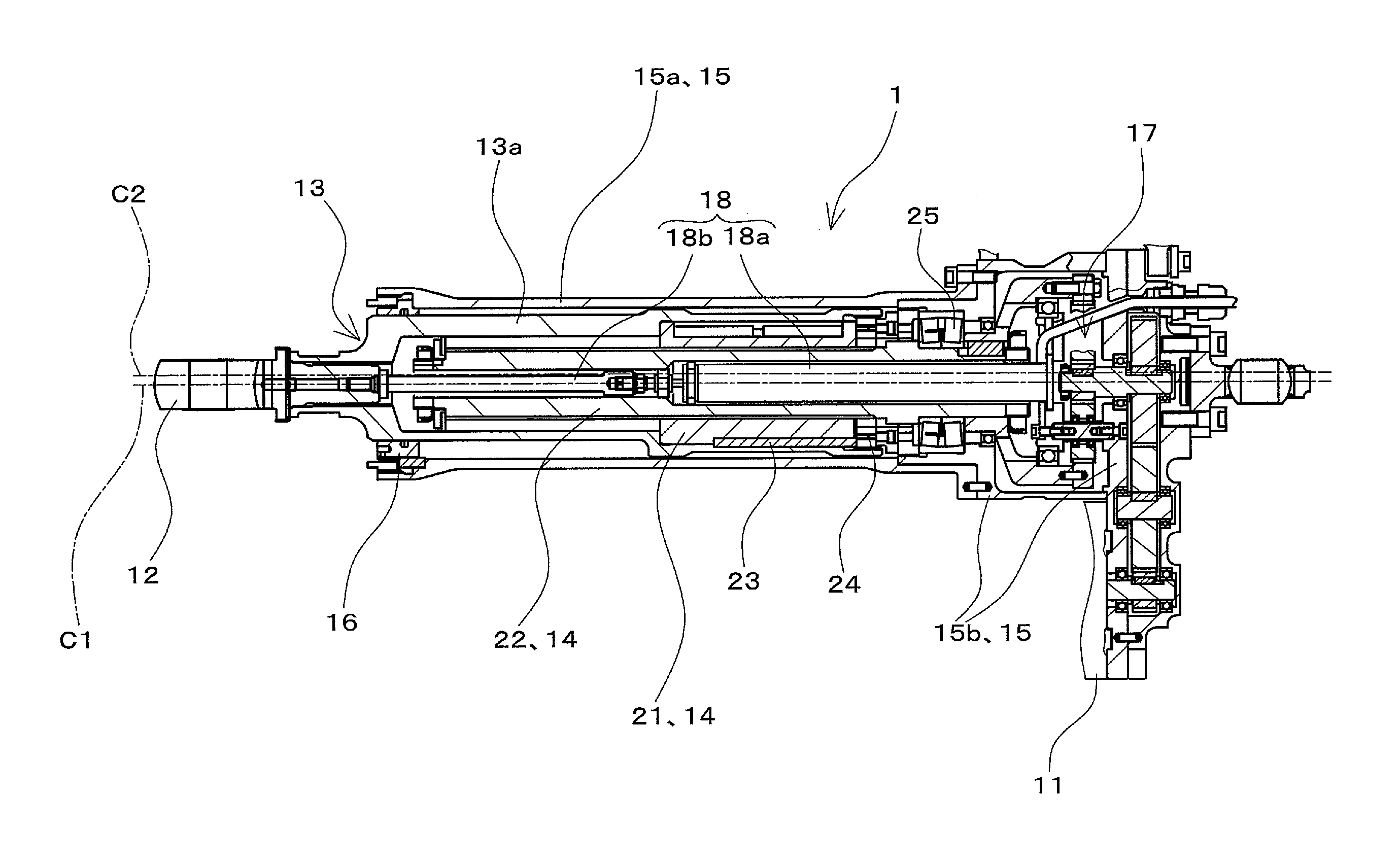
[0031]An embodiment for implementing the present invention will be hereinafter described with reference to the drawings. The following embodiment will be described, taking, as an example, a mode in which an actuator is used as a moving surface driving device for aircrafts for driving a moving surface of an aircraft. However, the present invention is not limited to the mode taken as an example in the following embodiment, and can be widely applied to actuators that convert a direction of action of driving force between a rotational direction and a linear direction and drive equipment. For example, the present invention can be applied to actuators used in aircrafts, helicopters, or flying objects.

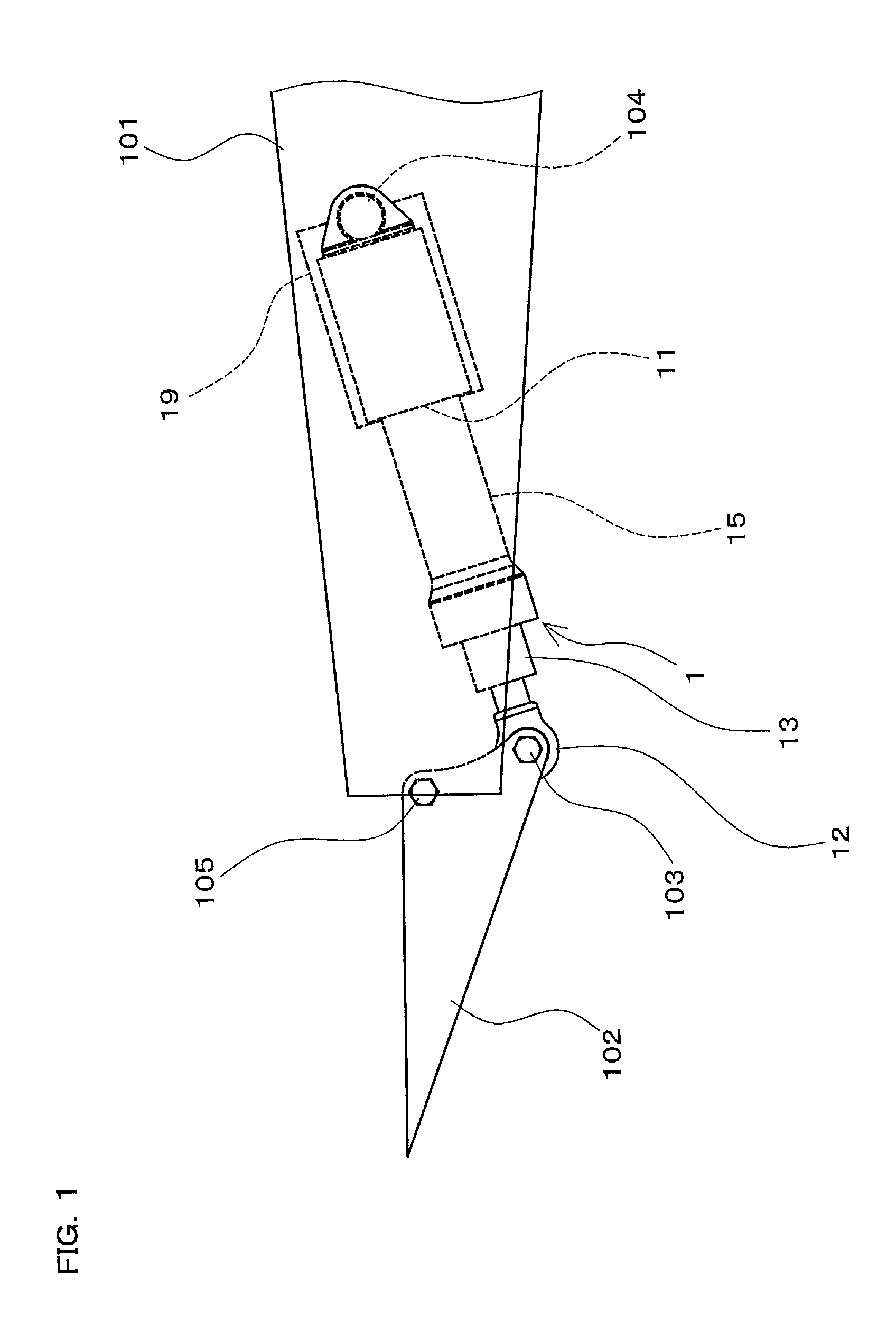
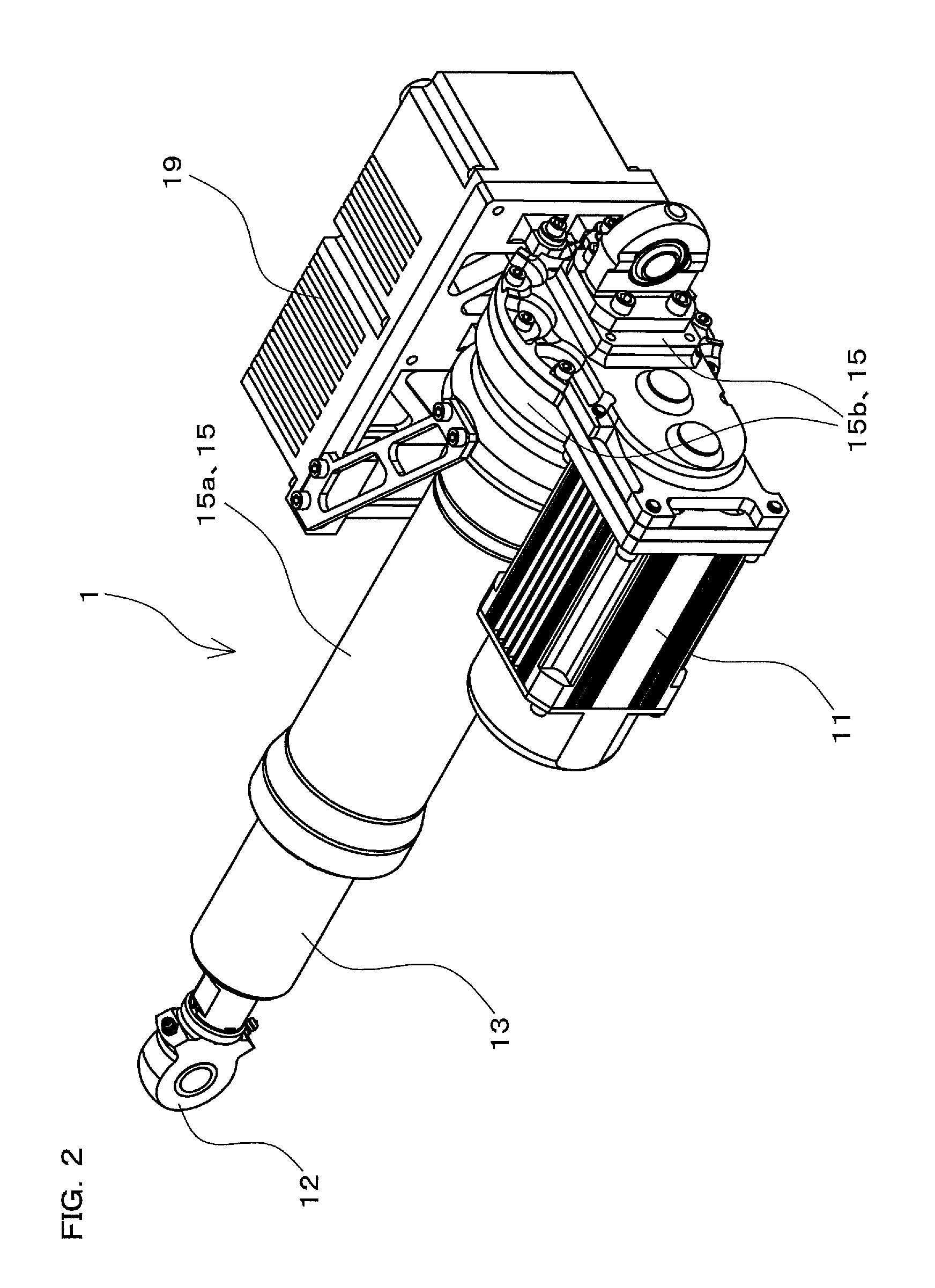
[0032]FIG. 1 is a schematic view of an actuator 1 according to an embodiment of the present invention in a state of being attached to a wing 101 and a control surface 102 of an aircraft. The actuator 1 shown in FIG. 1 is installed in the aircraft, whose wing 101 and control surface 102 are sh...


PUM


Abstract

A linear drive portion is fixed to a piston. A nut portion and a screw portion relatively rotate, and a direction of action of driving force is converted between a rotational direction and a linear direction. The piston is installed within a case. The inner circumference of a piston sliding portion fixed within the case slidably supports the outer circumference of the piston. The nut portion is displaced with the piston, and the screw portion rotates in conjunction with a rotational drive portion. The piston is installed so as to be able to slide in the axial direction of the case with respect to the piston sliding portion. The axis of the piston and the central position of the inner circumference of the piston sliding portion are set to be eccentric with respect to the axis of the screw portion and the nut portion.

Description

CROSS-REFERENCE TO RELATED APPLICATION[0001]This application claims priority to Japanese Patent Application No. 2011-266917. The entire disclosure of Japanese Patent Application No. 2011-266917 is hereby incorporated herein by reference.BACKGROUND OF THE INVENTION[0002]1. Field of the Invention[0003]The present invention relates to actuators that convert a direction of action of driving force between a rotational direction and a linear direction and drive equipment.[0004]2. Description of the Related Art[0005]Conventionally, as actuators for driving various kinds of equipment in different fields such as, for example, in the field of aircrafts, actuators that convert a direction of action of driving force between a rotational direction and a linear direction and drive equipment are used.[0006]U.S. Pat. No. 5,111,708 discloses an actuator that transmits, via a driving belt mechanism, rotational driving force generated by an electric motor, further converts this rotational driving forc...

Claims


Application Information

Patent Timeline
Patent Type & Authority Patents(United States)
IPC IPC(8): F16H3/06F16H25/24F16H27/02F16H29/02F16H21/18H02K7/06F16J1/10F16H29/20F16H25/20
CPCF16H25/20F16H25/2454H02K7/06F16H21/18F16J1/10F16H2025/2087F16H2025/2081Y10T74/18248
Inventor YASUI, TSUTOMU
Owner NABLESCO CORP
Why Eureka
Try Eureka