
Next fetch predictor return address stack

a prediction stack and address stack technology, applied in the field of microprocessors, can solve the problems of lower accuracy, instructions are fetched down the wrong path, and the sequential nature of the sequential nature of the program flow of the branch instruction, and achieve the effect of faster and more accurate branch prediction

Active Publication Date: 2016-08-02
APPLE INC
View PDF29 Cites 3 Cited by
  • Summary
  • Abstract
  • Description
  • Claims
  • Application Information

AI Technical Summary

Benefits of technology

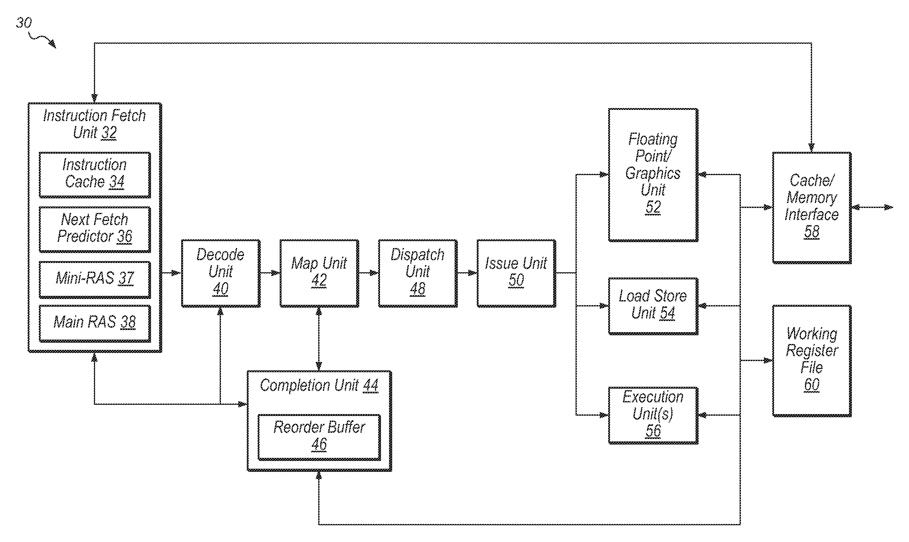
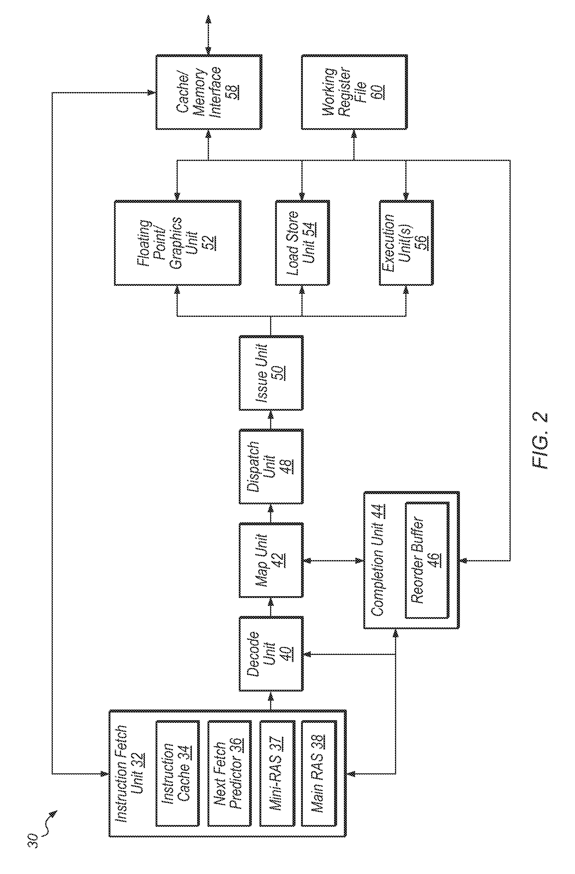
This patent describes systems and methods for faster and more accurate branch prediction in computer processing. The processor pipeline includes a next fetch predictor that can quickly generate branch prediction data, such as a branch direction and a branch target address. The processor pipeline also includes a return address stack (RAS) for storing return addresses for call branch instructions. The next fetch predictor includes entries for each branch instruction encountered in the program code, with an indicator to indicate if the branch instruction is a return branch instruction. The next fetch predictor may be performed for each fetch address used to fetch instructions, and if there is a hit to an entry corresponding to a return branch instruction, the prediction from the next fetch predictor may be ignored and the top of the RAS may be used as the branch target prediction. A separate RAS may be maintained early in the pipeline with the next fetch predictor to provide a first-stage branch target prediction for a new return branch instruction when there are one or more recently fetched call or return branch instructions in the early stages of the pipeline that have not yet updated the main RAS. These technical effects improve the speed and accuracy of branch prediction in computer processing.

Problems solved by technology

However, branch instructions can change the sequential nature of program flow.
However, the lower accuracy may lead to situations where instructions are fetched down the wrong path.
These mispredictions result in a stall in the processor pipeline while the fetching of instructions is redirected and the incorrectly fetched instructions are flushed.
A stall in a pipeline may prevent useful work from being performed during one or more pipeline stages.
Some stalls may last several clock cycles and significantly decrease processor performance

Method used


Image

  • Next fetch predictor return address stack
  • Next fetch predictor return address stack
  • Next fetch predictor return address stack

Examples


Embodiment Construction

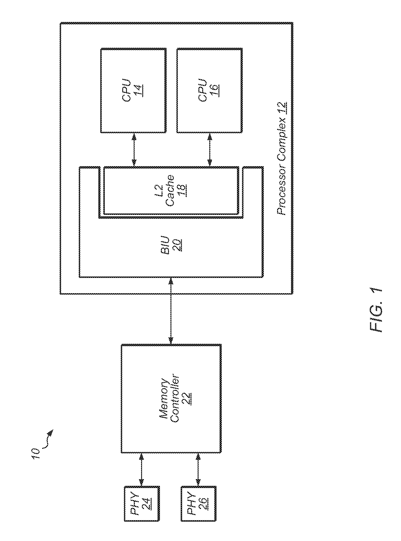
[0008]Systems and methods for faster and more accurate branch prediction. In one embodiment, a processor may be pipelined into multiple pipeline stages. The processor pipeline includes a next fetch predictor, which may quickly generate branch prediction data, such as a branch direction and a branch target address. In some embodiments, the next fetch predictor may be a single-cycle predictor for branch instructions. The next fetch predictor may predict branch targets at an early stage of the processor pipeline. The processor pipeline may also include a return address stack (RAS) for storing return addresses for call branch instructions. The RAS may be updated at a later stage of the pipeline.

[0009]In one embodiment, the next fetch predictor may include entries for each of the branch instructions encountered in the program code. An indicator may be stored in each entry of the next fetch predictor to indicate if the branch instruction is a return branch instruction. In one embodiment, ...


PUM


Abstract

A system and method for efficient branch prediction. A processor includes a next fetch predictor to generate a fast branch prediction for branch instructions at an early pipeline stage. The processor also includes a main return address stack (RAS) at a later pipeline stage for predicting the target of return instructions. When a return instruction is encountered, the prediction from the next fetch predictor is replaced by the top of the main RAS. If there are any recent call or return instructions in flight toward the main RAS, then a separate prediction is generated by a mini-RAS.

Description

BACKGROUND OF THE INVENTION[0001]1. Field of the Invention[0002]This invention relates to microprocessors, and more particularly, to branch prediction mechanisms.[0003]2. Description of the Relevant Art[0004]Modern day processor systems tend to be structured in multiple stages in a pipelined fashion. Typical pipelines often include separate units for fetching instructions, decoding instructions, mapping instructions, executing instructions, and then writing results to another unit, such as a register. An instruction fetch unit of a microprocessor is responsible for providing a constant stream of instructions to the next stage of the processor pipeline. Typically, fetch units utilize an instruction cache in order to keep the rest of the pipeline continuously supplied with instructions. The sequence of instructions being fetched is based upon a prediction of the program flow, which is normally sequential. However, branch instructions can change the sequential nature of program flow. T...

Claims


Application Information

Patent Timeline
Patent Type & Authority Patents(United States)
IPC IPC(8): G06F7/38G06F9/00G06F9/38G06F9/30
CPCG06F9/3806G06F9/30054G06F9/382G06F9/3848G06F9/323
Inventor HOLMAN, DOUGLAS C.GUNNA, RAMESH B.BLASCO-ALLUE, CONRADO
Owner APPLE INC
Learn More