Lighting device and receiver

a light source and receiver technology, applied in the direction of electromagnetic transmission, transmission, close-range type systems, etc., can solve the problems of cumbersome, if not impossible, and extraction of data modulated in ligh

Active Publication Date: 2016-08-02
KONINK PHILIPS ELECTRONICS NV
View PDF19 Cites 1 Cited by
  • Summary
  • Abstract
  • Description
  • Claims
  • Application Information

AI Technical Summary

Benefits of technology

[0012]Thereby, a lighting device is provided in which the different dimming modes used for dimming of the light output are compatible, in that different dimming modes and thereby different dimming methods may be employed for the same light source. By providing that regardless of which dimming mode is employed, an integrated light output power in a period of time T is modulated to embed the data information, a receiver for receiving light outputted from the lighting device can perform data extraction without the need of knowing the specific dimming method that is being used.
[0013]According to an embodiment of the lighting device, the code is modulated into the dimmed light output such that it is extractable by means of an integrate-and-dump process. This provides a convenient extraction method, which for a modulated light signal modulated using the compatible modulation method above, i.e. modulating the integrated light output power in a period of time, advantageously results in the same extracted code for e.g. a code modulation by means of amplitude modulation as well as for code modulation by means of pulse-width modulation.
[0015]According to an embodiment, two dimming modes are employed in the lighting device. A first mode is employed when the requested light output value DL is below a predetermined threshold level, and a second mode is employed when the requested light output value is above the predetermined threshold level. This is advantageous for providing a high power efficiency and yet accurate dimming. As an example, in an envisioned lighting device of the present inventive concept, being a LED lighting module, AM-D may be employed when the light output is dimmed down from 100% light output to, e.g., 10% light output, for the purpose of high power efficiency and yet achieving sufficiently accurate dimming. When the light output is further dimmed, i.e. below 10%, it is no longer preferable to use AM-D. The reason is that it is often difficult and costly to make a power source that provides accurate and yet stable low driving current for the lighting module. Instead, a different dimming method, such as PWM-D, may be employed. In PWM-D, the power source is periodically switched off by a percentage of the total time, while maintaining the (nominal) driving current when the power source is switched on. In this way, accurate and reliable deep dimming can be achieved.
[0022]According to an embodiment of the receiver, it further comprises a clock synchronization unit for synchronizing the integrate-and-dump process, which is advantageous.

Problems solved by technology

One of the key challenges for designing a visible light modulation method is that the data modulation shall be compatible with the lighting functionalities, i.e. such that the data modulated into the light emitted are generally invisible for the human eye.
An additional challenge, however, arises when a single lighting device is arranged to provide dimming with more than one dimming method, which may be applicable to increase the efficiency of the lighting device.
In these fixed dimming mode and fixed data modulation approaches, the receiver always needs to acquire the dimming information, e.g. which dimming mode is used, of a lighting device prior to the data reception process, i.e. extraction of data modulated in the light, which is cumbersome, if not impossible.

Method used


Image

  • Lighting device and receiver
  • Lighting device and receiver
  • Lighting device and receiver

Examples


Embodiment Construction

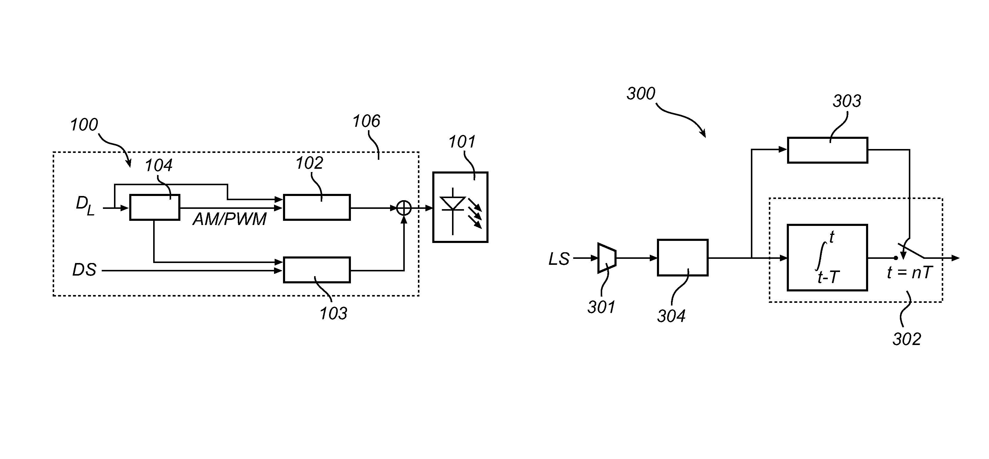
[0036]The present inventive concept is based on providing a code modulation method, herein under referred to as Compatible Amplitude Modulation, CAM, which provides a compatibility of code modulation in a dimmable lighting system. The CAM is based on in a lighting device, which may employ multiple dimming modes, each representing dimming the light output from the lighting device by means of a respective dimming method, controlling the instantaneous dimmed light output from the lighting device such that the integrated value of the dimmed light output during a time period T is modulated to embed a code. The code may then subsequently be extracted from the outputted modulated light by means of an integrate-and-dump process, without knowledge of the dimming method and / or dimming level of the lighting device.

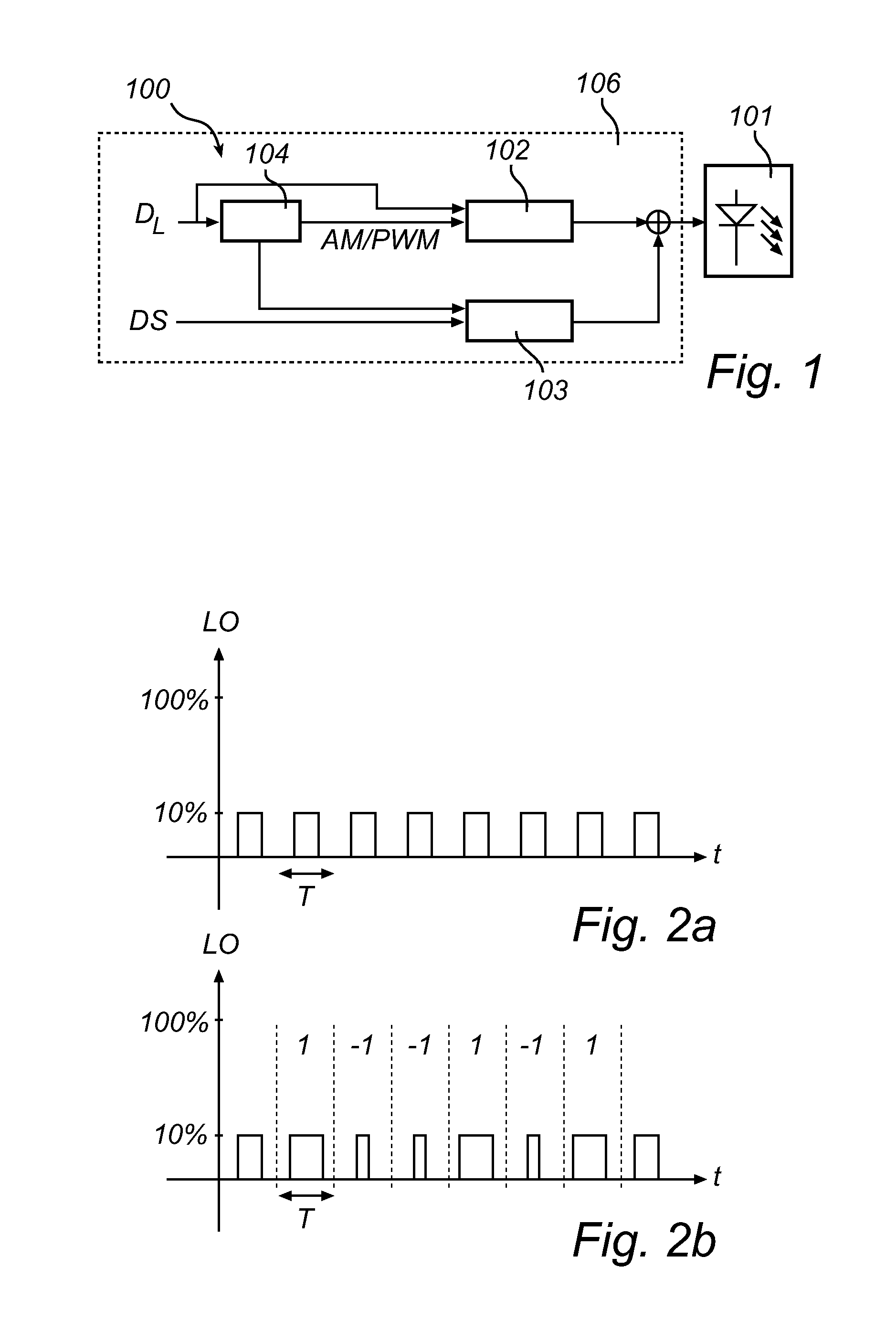
[0037]As a way of illustration, CAM is first described for a lighting device utilizing two modes of dimming. FIG. 1, details a schematic block diagram of an embodiment of a lighting ...


PUM


Abstract

There is provided a method and corresponding lighting device (100), and a receiver, which employs code modulation which provides a compatibility of code modulation in a dimmable lighting system. The lighting device comprises means for dimming the output light (102), which employs multiple dimming modes, each representing dimming the light output from lighting device by means of a respective dimming method, and means for embedding a code in the light output (103). The means for embedding a code in the light output employs code modulation which is based on controlling the instantaneous dimmed light output from the lighting device such that the integrated value of the dimmed light output during a time period T is modulated to embed the code. The code may then subsequently be extracted from the modulated light by means of an integrate-and-dump process at a receiver, without knowledge of the dimming method and / or dimming level of the lighting device.

Description

FIELD OF THE INVENTION[0001]The present invention relates to the field of code modulated lighting devices, and more particularly to a lighting device employing multiple dimming modes and a code modulation method, receiver, and lighting system for such a lighting device.BACKGROUND OF THE INVENTION[0002]Visible light communications can bring significant benefit to realize various intelligent lighting applications, such as easy commissioning, state information read out, and point and control etc., for light emitting diode (LED) lighting modules. One of the key challenges for designing a visible light modulation method is that the data modulation shall be compatible with the lighting functionalities, i.e. such that the data modulated into the light emitted are generally invisible for the human eye.[0003]In particular, many advanced LED lighting systems allow lighting functionalities like dimming, e.g. for the sake of energy saving in an office environment or ambience creation in a resta...

Claims


Application Information

Patent Timeline
Patent Type & Authority Patents(United States)
IPC IPC(8): H04B10/00H04B10/116H05B33/08H04B10/114H05B44/00
CPCH05B33/0845H04B10/116H04B10/1141H05B45/10
Inventor YANG, HONGMINGSCHENK, TIM CORNEEL WILHELMUS
Owner KONINK PHILIPS ELECTRONICS NV
Why Eureka
Try Eureka