Spinal stimulator systems for restoration of function

a stimulator and spinal cord technology, applied in the field of spinal cord stimulator systems for restoring function, can solve the problems of limited attempts to restore function in neurologically impaired subjects, little progress in realizing the restoration of normal function of damaged nerve tissue, and no permanent remodeling of the nervous system

Active Publication Date: 2016-08-09
CALIFORNIA INST OF TECH +2
View PDF246 Cites 54 Cited by
  • Summary
  • Abstract
  • Description
  • Claims
  • Application Information

AI Technical Summary

Benefits of technology

[0020]In some embodiments, when at least partially activated, the at least one selected spinal circuit produces improved neurological function including at least one of voluntary movement of muscles involved in at least one of standing, stepping, reaching, grasping, voluntarily changing positions of one or both legs, voluntarily changing positions of one or both arms, voiding the subject's bladder, voiding the subject's bowel, postural activity, and locomotor activity. In some embodiments, when at least partially activated, the at least one selected spinal circuit produces improved neurological function including at least one of improved autonomic control of at least one of voiding the subject's bladder, voiding the subject's bowel, cardiovascular function, respiratory function, digestive function, body temperature, and metabolic processes. In some embodiments, when at least partially activated the at least one selected spinal circuit produces improved neurological function including at least one of an autonomic function, sexual function, motor function, vasomotor function, and cognitive function.

Problems solved by technology

Further, none have been aimed at permanent remodeling of the nervous system.
Attempts to restore function in neurologically impaired subjects have been limited to adjunctive modalities, such as physical and occupational therapy with emphasis on adaptation to disability.
Little progress has been achieved in actually restoring normal functional capacity to damaged nerve tissue with the use of an implantable neurostimulator.
Further, no one has shown the ability to regain voluntary movements, and / or to recover autonomic, sexual, vasomotor, and / or improved cognitive function after a motor complete SCI.

Method used


Image

  • Spinal stimulator systems for restoration of function
  • Spinal stimulator systems for restoration of function
  • Spinal stimulator systems for restoration of function

Examples


first embodiment

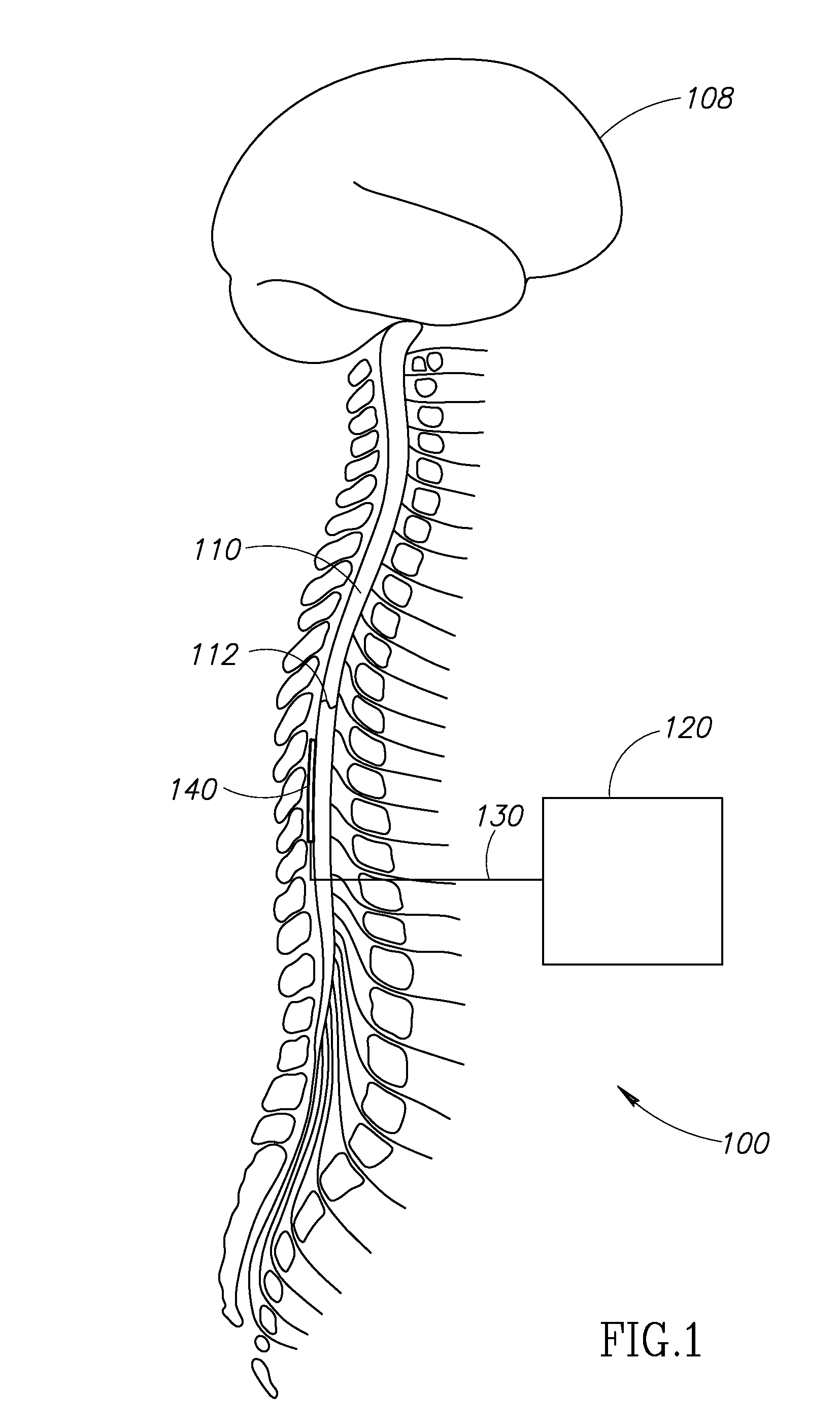
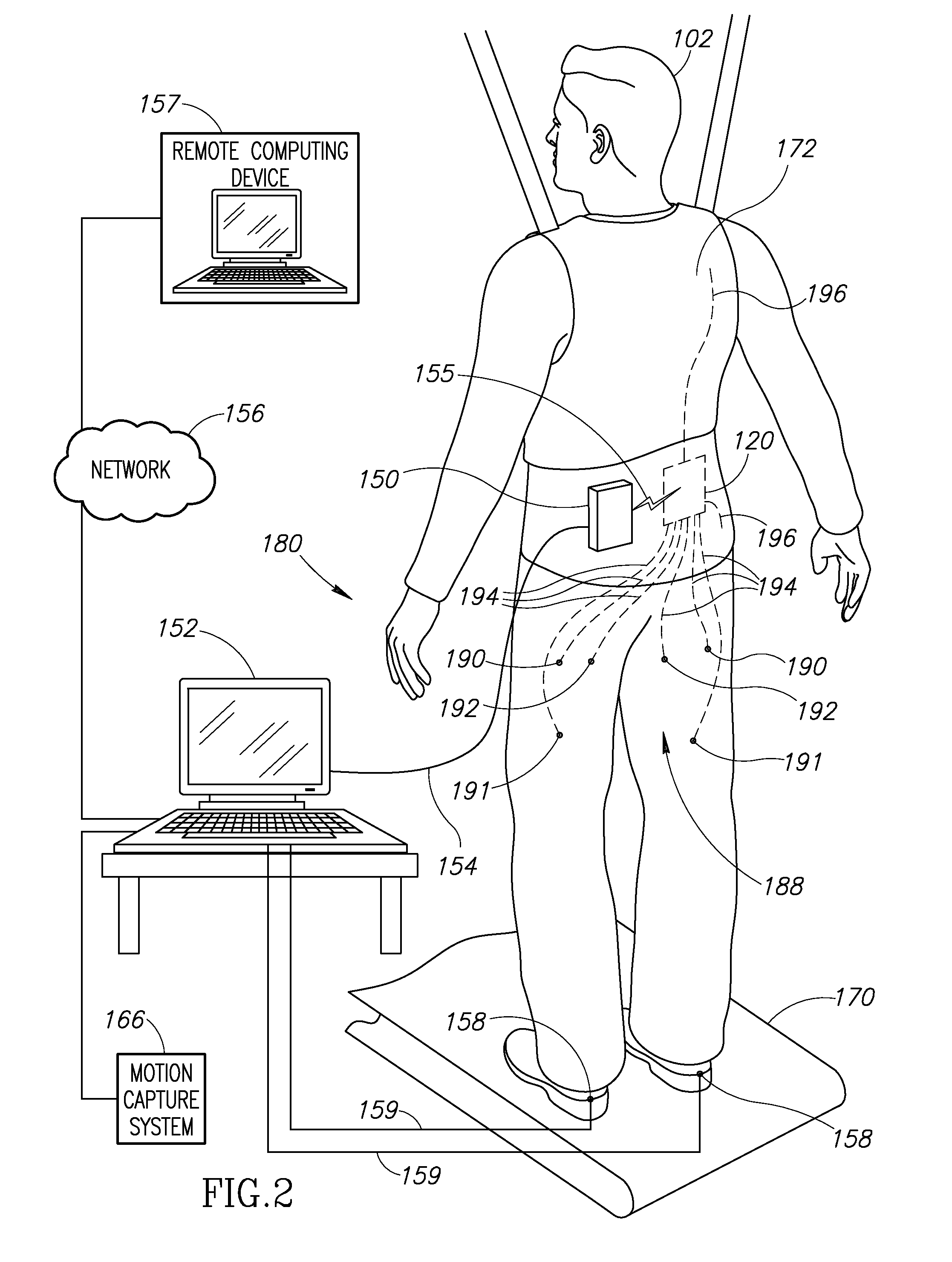
[0106]FIG. 5 is a block diagram of a first embodiment of a system 200. The system 200 includes an implantable assembly 202 substantially similar to the assembly 100 described above, and an external system 204 substantially similar to the external system 180 described above. Therefore, only components of the assembly 202 that differ from those of the assembly 100, and components of the external system 204 that differ from those of the external system 180 will be described in detail. For ease of illustration, like reference numerals have been used to identify like components in FIGS. 1-3 and 5.

[0107]The assembly 202 includes a neurostimulator device 220, the one or more leads 130, and the electrode array 140, and the connections 194. The assembly 202 may also include the reference wires 196 (see FIG. 2). By way of a non-limiting example, the assembly 202 may include the two reference wires illustrated in FIG. 2. In the embodiment illustrated, the connections 194 include sixteen wires,...

second embodiment

[0151]FIG. 10 is a block diagram of an implantable assembly 300. For ease of illustration, like reference numerals have been used to identify like components in FIGS. 1-3, 5, and 10. The assembly 300 may be configured to communicate with the external controller 270 via the communication connection 155A. Optionally, the assembly 300 may receive power wirelessly from the external wireless power circuit 280 via inductive coupling over the power transfer connection 155B.

[0152]In addition to providing complex stimulation patterns to body tissue (e.g., neurological tissue), the assembly 300 is configured to also provide electrical stimulation directly to muscles (not shown) that will cause the muscle to move (e.g., contract) to thereby augment the improved neurological function provided by the complex stimulation patterns alone. The assembly 300 is configured to provide one or more complex stimulation patterns to 16 or more individually addressable electrodes for purposes of providing imp...

third embodiment

[0169]FIG. 11 is a block diagram of a first embodiment of a system 400. The system 400 includes an implantable assembly 402 substantially similar to the assembly 100 described above, and an external system 404 substantially similar to the external system 180 described above. Therefore, only components of the assembly 402 that differ from those of the assembly 100, and components of the external system 404 that differ from those of the external system 180 will be described in detail. For ease of illustration, like reference numerals have been used to identify like components in FIGS. 1-3, 5, and 10-12B.

[0170]The assembly 402 includes a neurostimulator device 420, the electrode array 140, and the one or more traces 130. The neurostimulator device 420 is connected by a controller interface bus 437 to an implantable muscle stimulator package 438, and an EMG module 446. The neurostimulator device 420 is configured to interface with and control both the implantable muscle stimulator packa...


PUM


Abstract

Described are devices including stimulation assemblies connectable to a plurality of electrodes. The plurality of electrodes can be configured to connect to a spinal cord at a location below a lesion of the spinal cord. The stimulation assembly can be configured to deliver stimulation to selected ones of the plurality of electrodes when the stimulation assembly is connected to the plurality of electrodes when located below the lesion of the spinal cord. Methods of using the devices are also described.

Description

CROSS-REFERENCE TO RELATED APPLICATION(S)[0001]This application claims priority under 35 U.S.C. §371 to International Patent Application PCT / US2012 / 030624 filed on Mar. 26, 2012, which claims the benefit of U.S. Provisional Application No. 61 / 467,107, filed Mar. 24, 2011, which are incorporated herein by reference in their entirety.STATEMENT REGARDING FEDERALLY SPONSORED RESEARCH OR DEVELOPMENT[0002]This invention was made with Government support under Grant No. EB007615, awarded by the National Institutes of Health. The Government has certain rights in this invention.BACKGROUND OF THE INVENTION[0003]1. Field of the Invention[0004]The present invention is directed generally to the field of medical electro-medical therapy devices, and more particularly to implantable stimulators and stimulator systems used in neurological rehabilitation for the treatment of traumatic and non-traumatic injury or illness.[0005]2. Description of the Related Art[0006]Prior art implantable neurostimulator...

Claims


Application Information

Patent Timeline
Patent Type & Authority Patents(United States)
IPC IPC(8): A61N1/37A61N1/36A61N1/05A61B5/00A61B5/0492A61B5/11A61B5/296
CPCA61N1/0553A61N1/36003A61N1/36103A61N1/36139A61N1/36125A61N1/0551A61B5/407A61B5/4076A61B5/4836A61B5/0492A61B5/1106A61B2505/09A61N1/36007A61N1/36067A61N1/36082A61N1/36107A61N1/3611A61N1/36114A61B5/296A61N1/37252
Inventor BURDICK, JOEL W.TAI, YU-CHONGNABER, JOHN F.KEYNTON, ROBERT S.EDGERTON, VICTOR REGGIEROY, ROLAND R.GERASIMENKO, YURYHARKEMA, SUSAN J.HODES, JONATHANANGELI, CLAUDIA A.NANDRA, MANDHEEREJ S.DESAUTELS, THOMAS ANTHONYUPCHURCH, STEVEN L.JACKSON, DOUGLAS J.TERRAFRANCA, NICHOLAS A.CHEN, YANGSHEN
Owner CALIFORNIA INST OF TECH
Why Eureka
Try Eureka