
Waterproof electronic receptacle connector

a technology for electronic receptacles and connectors, applied in the direction of coupling devices, coupling bases/cases, securing/insulating coupling contact members, etc., can solve the problems of high cost of conventional sealing materials and additional costs for manufacturers, and achieve the effect of reducing the amount of sealing materials and preventing moistur

Active Publication Date: 2016-08-09
ADVANCED CONNECTEK INC
View PDF8 Cites 4 Cited by
  • Summary
  • Abstract
  • Description
  • Claims
  • Application Information

AI Technical Summary

Benefits of technology

The design effectively prevents moisture from entering the connector with a reduced amount of sealing material, reducing costs and drying time, while maintaining waterproof functionality.

Problems solved by technology

However, the cost of the conventional sealing material is high; additionally, the sealing material is commonly available in a liquid form, for forming the waterproof adhesive bulk in larger areas, so the sealing material requires a drying procedure for a longer time, resulting into additional costs for the manufacturer.

Method used


Image

  • Waterproof electronic receptacle connector
  • Waterproof electronic receptacle connector
  • Waterproof electronic receptacle connector

Examples


first embodiment

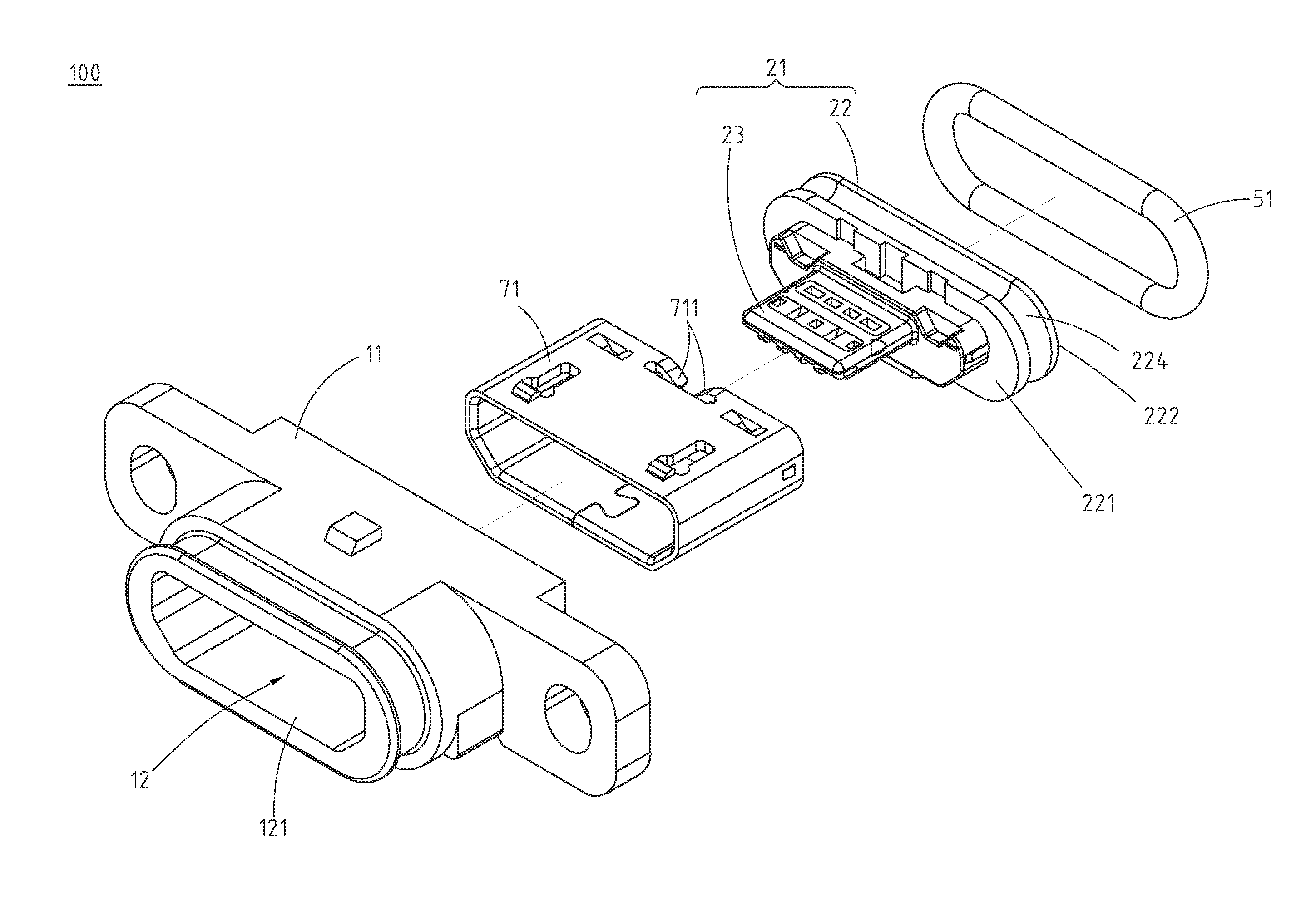
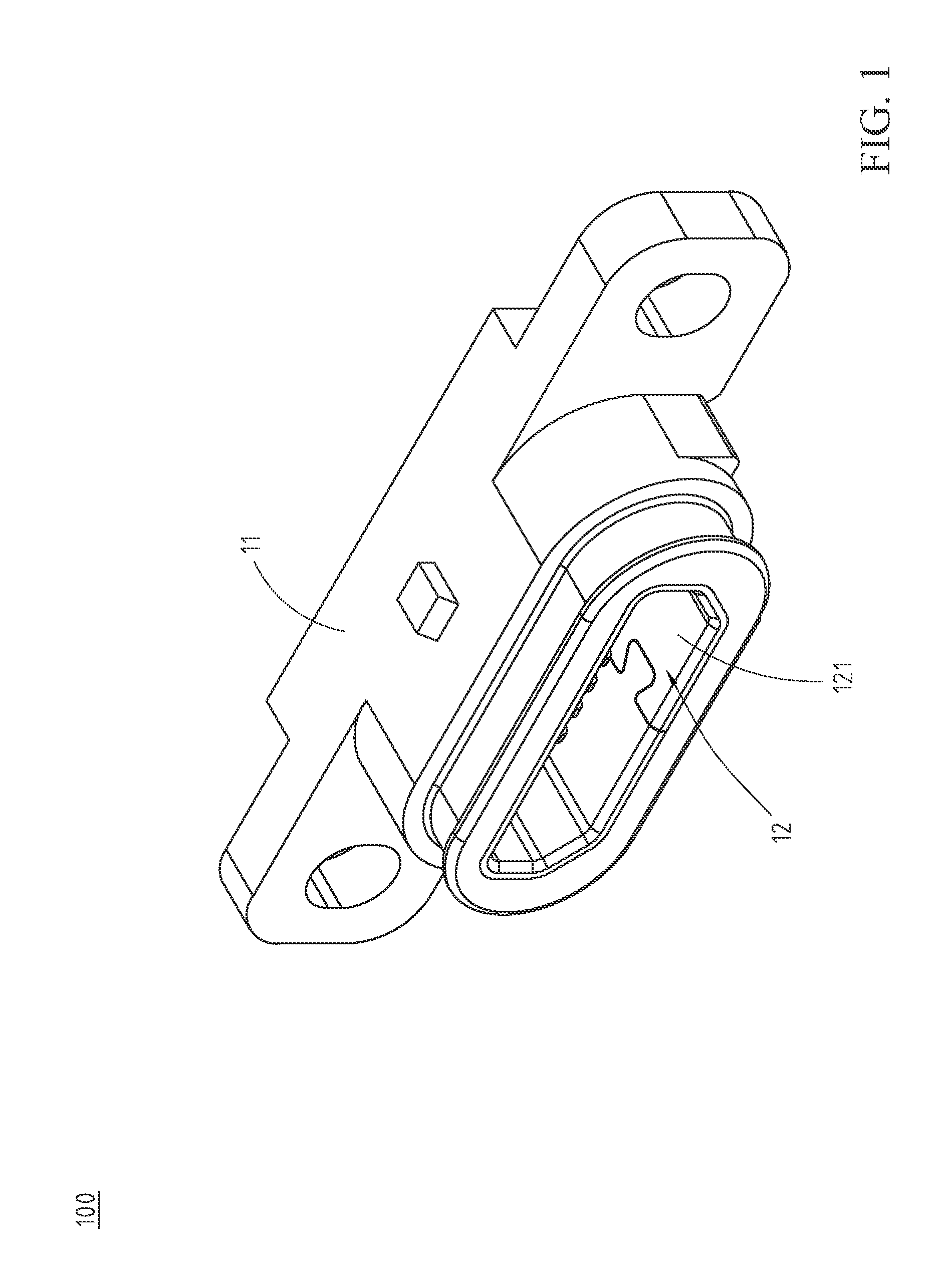
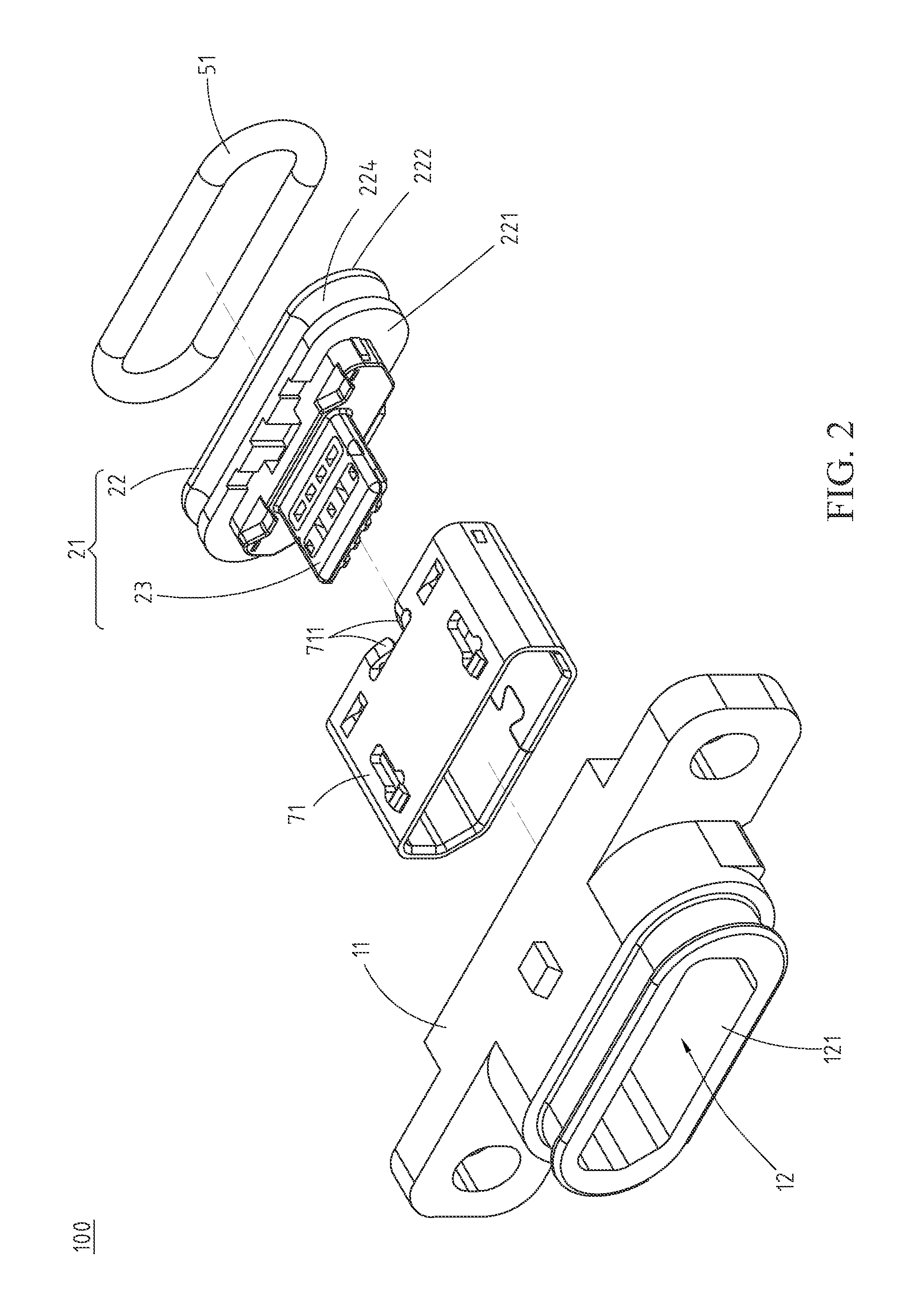
[0021]Please refer to FIG. 1, FIG. 2, FIG. 3, and FIG. 4A, which illustrate a waterproof electronic receptacle connector 100 of the disclosure and are respectively a perspective view, an exploded view, another exploded view and a lateral cross sectional view of the waterproof electronic receptacle connector 100. The waterproof electronic receptacle connector 100 is a Micro USB or a Mini USB electronic connector, but embodiments are not limited thereto.

[0022]The waterproof electronic receptacle connector 100 is applicable for mobile telecommunication devices, notebooks, digital cameras or other electronic devices. In this embodiment, the waterproof electronic receptacle connector 100 includes a plastic-core housing 11, an insulation housing 21, a plurality of terminal grooves 25, a plurality of terminals 41, a waterproof ring gasket 51, and a sealing material 61 (such as a waterproof adhesive bulk).

[0023]The plastic-core housing 11 is a plastic hollowed housing. A through hole 12 is ...

second embodiment

[0035]Similar to the previous embodiments, in the second embodiment, the plurality of terminal grooves 25 is provided and the plurality of terminals 41 is configured in the plurality of terminal grooves 25 and passing through the base 22, but embodiments are not limited thereto; in some implementation aspects, the insulation housing 21 and the plurality of terminals 41 are formed integrally as a whole. The method, such as insert molding, over molding, other molding techniques or the combinations thereof, can be used for forming the components integrally, which is not used to limit the present invention. In this case, the plurality of terminal grooves 25 is absent, and the plurality of terminals 41 is directly passing through the base 22. However, since the thermal expansion coefficients between the terminal 41 made of metal and the insulation housing 21 made of plastic are different, when the waterproof electronic receptacle connector 100 is heated during manufacturing processes, fo...


PUM


Abstract

A waterproof electronic receptacle connector includes a plastic-core housing, an insulation housing, terminals, a waterproof ring gasket and a sealing material. The plastic-core housing includes a through hole. The insulation housing is configured in the through hole and includes a base and a tongue plate. The base includes an inner side plane facing toward the through hole and an outer side plane facing toward an outside of the through hole. The tongue plate is extended from the inner side plane. The terminals are passing through the base. Each terminal includes a contacting end extended from the tongue plate and a welding end connected to the contacting end and extruded from the outer side plane. The waterproof ring gasket is abutted between the base and an inner wall of the through hole. The sealing material is formed on the outer side plane to fill gaps between the terminal and the base.

Description

CROSS-REFERENCES TO RELATED APPLICATIONS[0001]This non-provisional application claims priority under 35 U.S.C. §119(a) on Patent Application No. 103203362 filed in Taiwan, R.O.C. on Feb. 26, 2014, the entire contents of which are hereby incorporated by reference.FIELD OF THE INVENTION[0002]The disclosure relates to an electronic receptacle connector, and particularly to a waterproof electronic receptacle connector.BACKGROUND[0003]USB, universal serial bus, is a common electronic connector interface applied to electronic devices. In order to be smaller and portable, a micro USB electrical connector is developed, which is usually equipped with a connection hole and a corresponding transmission line for various portable electronic apparatuses such as a smart mobile communications device and a digital camera.[0004]Conventionally, a Micro USB electronic connector includes an insulation housing and a tongue plate structure formed at the front portion of the insulation housing, a plurality...

Claims


Application Information

Patent Timeline
Patent Type & Authority Patents(United States)
IPC IPC(8): H01R13/40H01R13/52H01R12/72
CPCH01R13/5202H01R13/521H01R12/724
Inventor CHIEN, MIN-LUNGCHANG, MING-YUNG
Owner ADVANCED CONNECTEK INC
Learn More