
Printing control apparatus and printing control method

a control apparatus and control method technology, applied in printing, printing, power drive mechanisms, etc., can solve the problems of image quality deterioration and long flying time of ink discharge, and achieve the effect of suppressing image quality deterioration

Active Publication Date: 2016-08-16
SEIKO EPSON CORP
View PDF8 Cites 1 Cited by
  • Summary
  • Abstract
  • Description
  • Claims
  • Application Information

AI Technical Summary

Benefits of technology

The invention is about a printing control apparatus and method that can improve image quality by reducing the effects of print media. This is achieved by reducing the number of ink droplets and the size of the ink droplets that affect image quality. By controlling the printing resolution and the number of nozzle rows used in the printing process, the invention can optimize the image quality and reduce the likelihood of blurring or other distortion of the printed text. Additionally, the invention can reduce variations in nozzle intervals that may occur when the printing head is tilted.

Problems solved by technology

Meanwhile, when the sub-droplets are deviated from the main droplets and landed onto the printing medium, the sub-droplets are preset in the printing result so that the image quality is deteriorated.
As much as the PG is wide, the flying time of the ink discharged is likely to be long.

Method used


Image

  • Printing control apparatus and printing control method
  • Printing control apparatus and printing control method
  • Printing control apparatus and printing control method

Examples


modification example

4. Modification Example

[0077]The invention is not limited to the above described embodiment, and can be performed in accordance with aspects within a range which does not depart from a gist thereof, for example, modification examples to be described below can be adopted. A configuration in which the embodiment described above and modification examples are appropriately combined is included in a disclosure range of the invention. In description of the modification examples hereinbelow, description of common issues same as the above described embodiment will not be repeated.

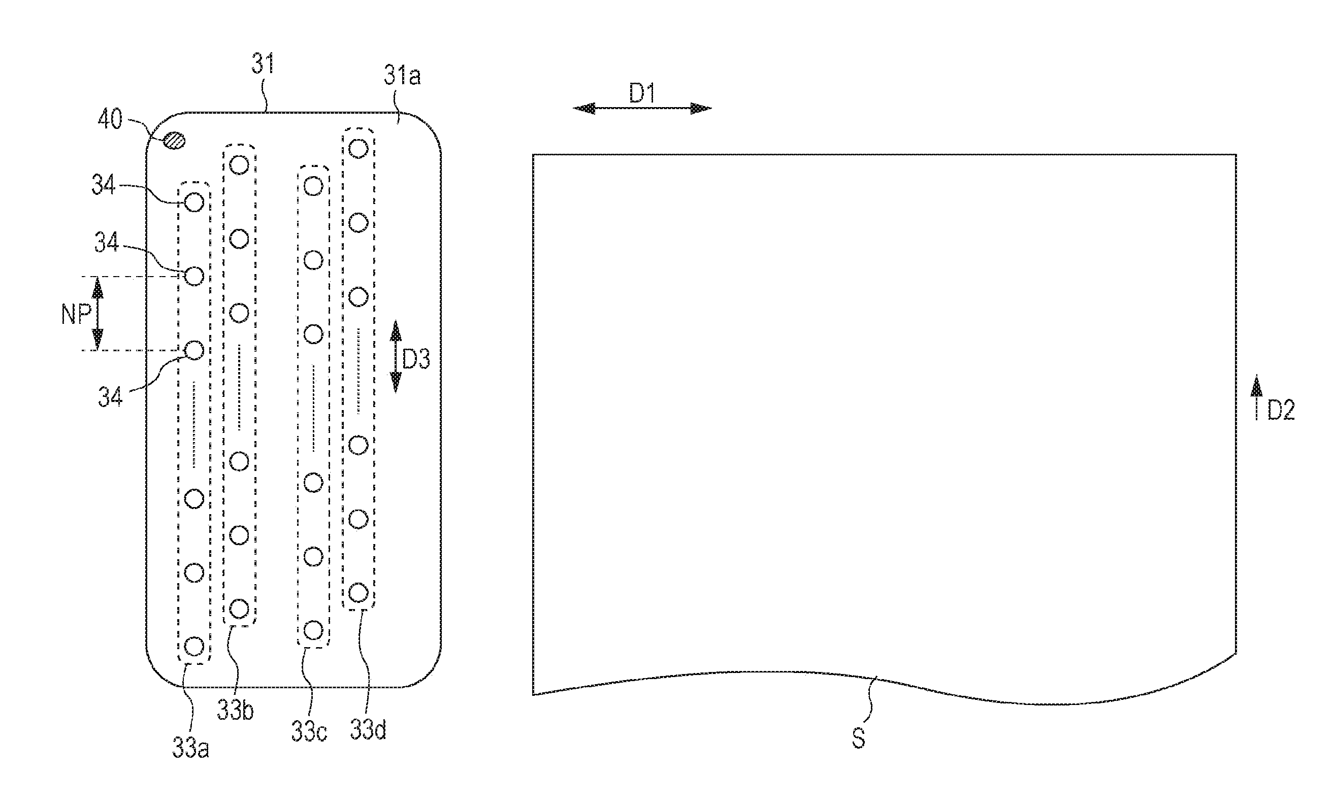
[0078]When the printing section 30 corresponds to color printing, a description same as a description relating to the data and the configurations of the K ink, is applied to data and configurations of the other color of ink. That is, in the same manner as that of the nozzle rows 33a, 33b, 33c, and 33d discharging the K ink, a plurality of the nozzle rows discharging the same types of ink are provided in the printin...


PUM


Abstract

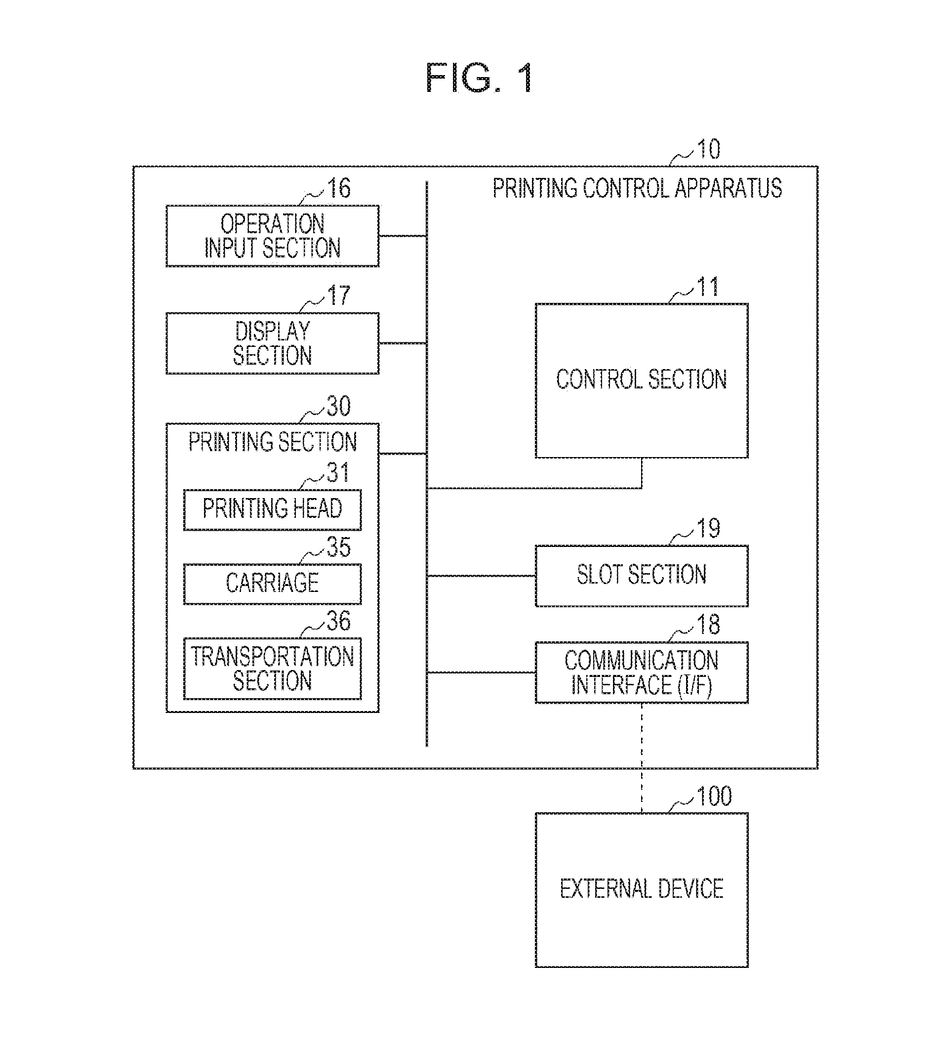
A printing control apparatus which realizes printing by controlling a printing head including nozzle rows in which a plurality of nozzles are arranged in a predetermined nozzle row direction, the apparatus including a control section that controls the printing head in which the plurality of nozzle rows discharging same types of ink are disposed to be deviated from the nozzle row direction, in which the control section is capable of selecting and performing any one of a first printing mode in which the printing is performed by setting a platen gap which is a distance from a platen supporting the printing medium on which the ink is discharged to the printing head as a first platen gap, and a second printing mode in which the printing is performed by setting the platen gap as a second platen gap which is narrower than the first platen gap.

Description

BACKGROUND[0001]1. Technical Field[0002]The present invention relates to a printing control apparatus and a printing control method.[0003]2. Related Art[0004]An ink jet printer is known which performs printing by discharging ink to a printing medium using a printing head which includes nozzle rows in which a plurality of nozzles capable of discharging the ink are arranged in a nozzle row direction. In the ink jet printer, a platen gap (hereinafter, PG) which is a distance from a platen supporting the printing medium on which the ink is discharged to the printing head is varied according to differences of the printing medium being used, or the like.[0005]In addition, in the ink jet printer, when discharging the ink from the nozzles, together with discharged ink droplets (the main droplets), droplets which are so-called satellites, or the like, which are fine compared to the main droplets are discharged. The satellites are referred to as sub-droplets. In addition, a part of the main d...

Claims


Application Information

Patent Timeline
IPC IPC(8): B41J2/045
CPCB41J2/04551B41J2/04586B41J2/2128B41J29/38B41J25/308
Inventor FUKAZAWA, MASAHIRO
Owner SEIKO EPSON CORP
Learn More