Lens design and method for minimizing visual acuity variation experienced by myopia progressors

a technology of myopia progressor and lens design, applied in the field of ophthalmic lenses, can solve the problems of hyperopia, eye growth too long, and eye growth not long enough

Active Publication Date: 2016-08-16
JOHNSON & JOHNSON VISION CARE INC
View PDF12 Cites 4 Cited by
  • Summary
  • Abstract
  • Description
  • Claims
  • Application Information

AI Technical Summary

Benefits of technology

[0009]The lens designs of the present invention overcomes the limitations of the prior art by ensuring comparable or better distance vision correction with minimization of visual acuity variation experienced by progressing myopes over the course of time.
[0010]In accordance with one aspect, the present invention is directed to an ophthalmic lens for minimizing visual acuity variation for a progressing myope. The lens comprises a lens having a center and at least one peripheral zone surrounding the center and having a different dioptric power than at the center. The lens has power profile selected from the group consisting of a power profile with spherical aberration, a multifocal power profile, a freeform power profile, and a segmented freeform power profile. The power profile is determined based on an initial paraxial power of a myopia progressor and a defined myopia progression rate over a specific time period, so that changes in visual acuity at a beginning of the time period and at an end of the time period are minimized.
[0011]In accordance with another aspect, the present invention is directed to a method for minimizing visual acuity variation for a progressing myope. An ophthalmic lens is provided having a center and at least one peripheral zone surrounding the center and having a different dioptric power than at the center. The power profile of the lens is selected from the group consisting of a power profile with spherical aberration, a multifocal power profile, a freeform power profile, and a segmented freeform power profile. The power profile of the lens is determined based on a paraxial power of a myopia progressor and a defined myopia progression rate over a specific time period, so that changes in visual acuity at a beginning of the time period and at an end of the time period are minimized.
[0012]The contact lens of the present invention is designed with a power profile to minimize visual acuity variation experienced by progressing myopes over the course of time.
[0013]The lens design of the present invention may also be customized to achieve both good foveal vision correction and minimal variation of visual performance over time based on the subject eyes' average pupil size.
[0014]The contact lens design of the present invention provides a simple, cost-effective and efficacious means and method for correcting myopia for progressing myopes whose rates are increasing throughout the world.

Problems solved by technology

Myopia typically develops because the axial length of the eye grows to be longer than the focal length of the optical components of the eye, that is, the eye grows too long.
Hyperopia typically develops because the axial length of the eye is too short compared with the focal length of the optical components of the eye, that is, the eye does not grow long enough.
High myopia is also associated with an increased risk of retinal disease, cataracts, and glaucoma.
However, the corrective approach to the conditions does not address the cause of the condition, but is merely prosthetic or intended to address symptoms.
Moreover, conventional corrective approaches for spherical equivalent power, such as spectacles and contact lenses, are effective at correcting the static focus error, but do not address the dynamic change in gross focus error over time, resulting in poor vision outcome shortly after the dispensing of lenses.
Astigmatic errors of focus cause the image of a point source of light to form as two mutually perpendicular lines at different focal distances.

Method used


Image

  • Lens design and method for minimizing visual acuity variation experienced by myopia progressors
  • Lens design and method for minimizing visual acuity variation experienced by myopia progressors
  • Lens design and method for minimizing visual acuity variation experienced by myopia progressors

Examples


Embodiment Construction

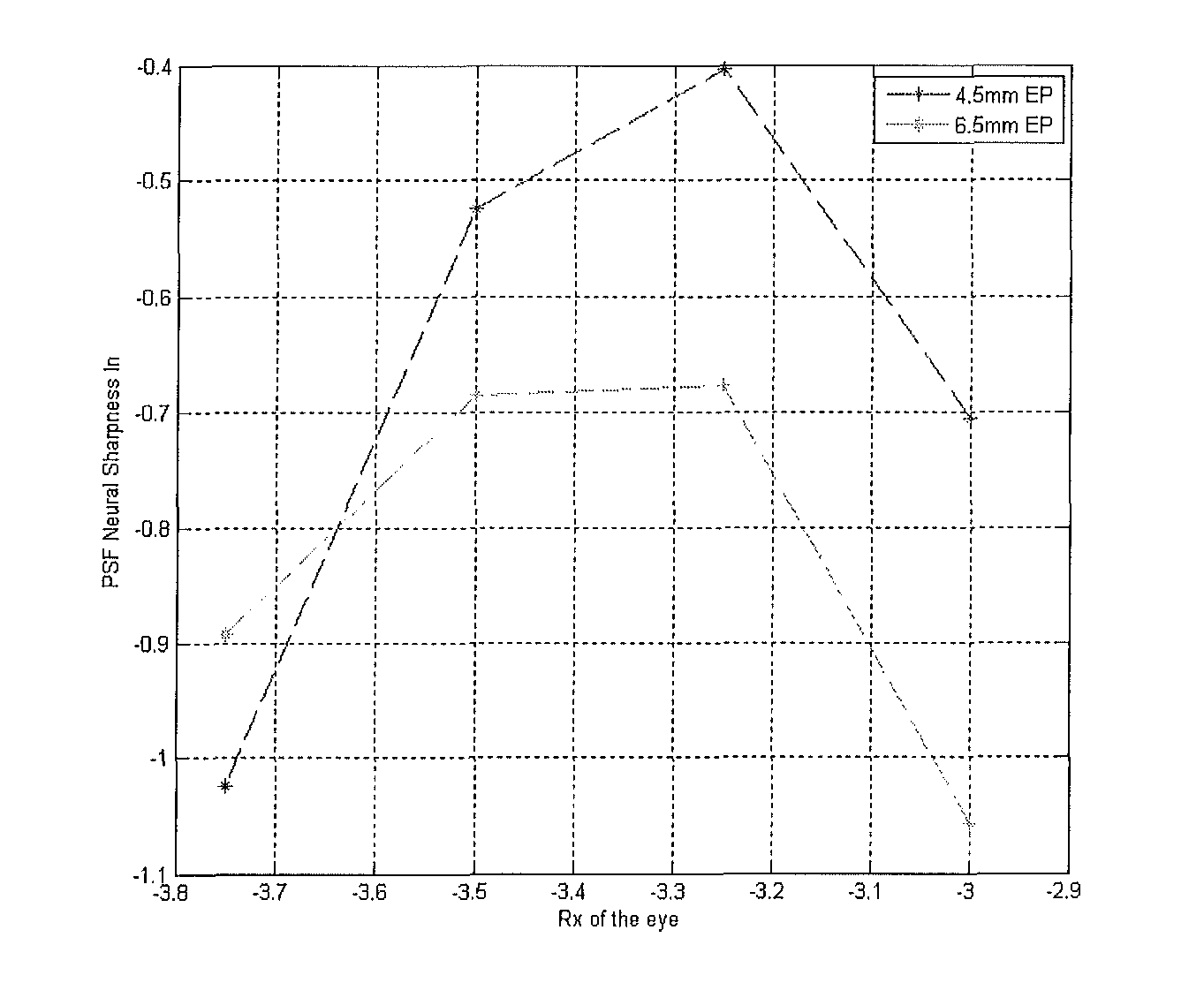
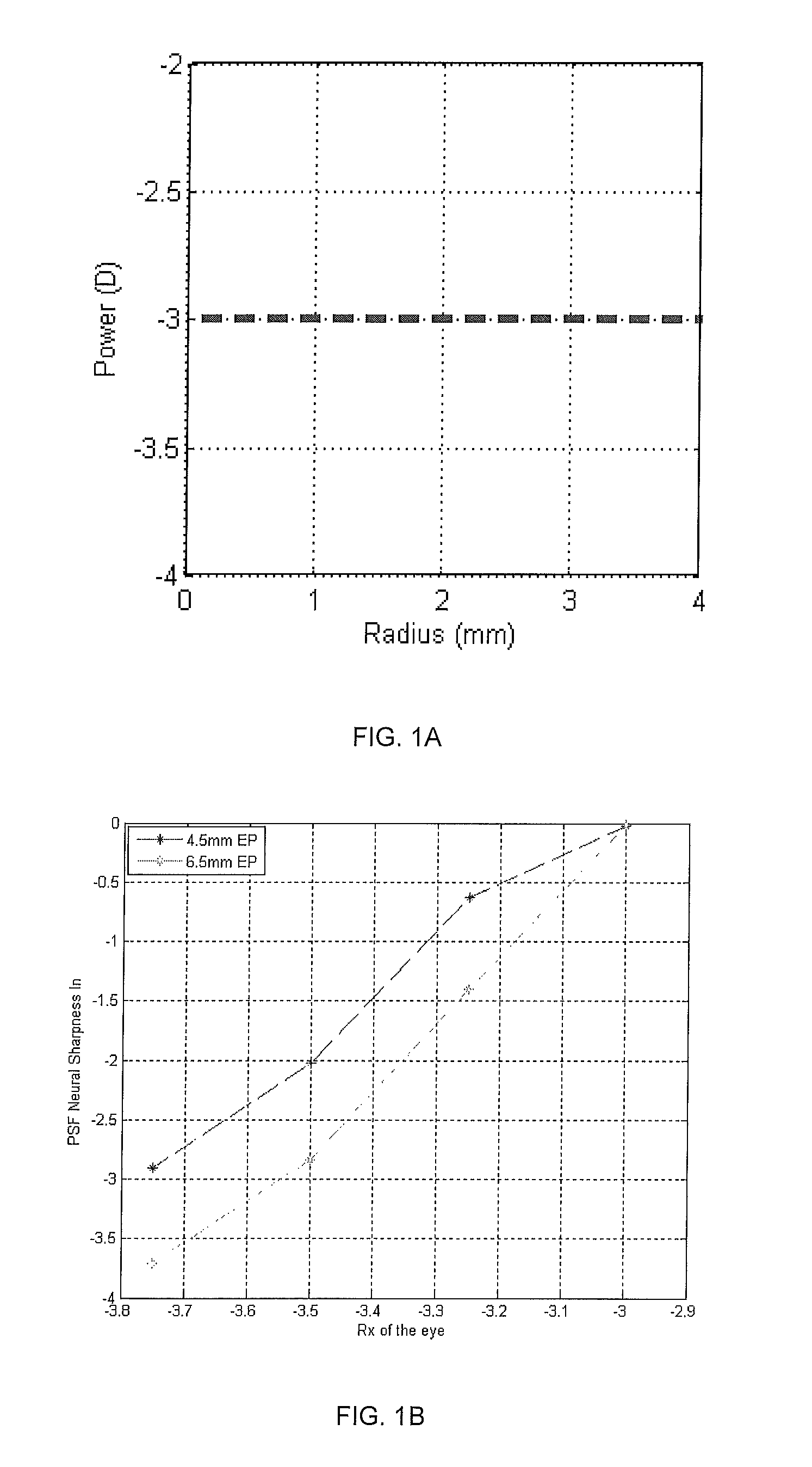
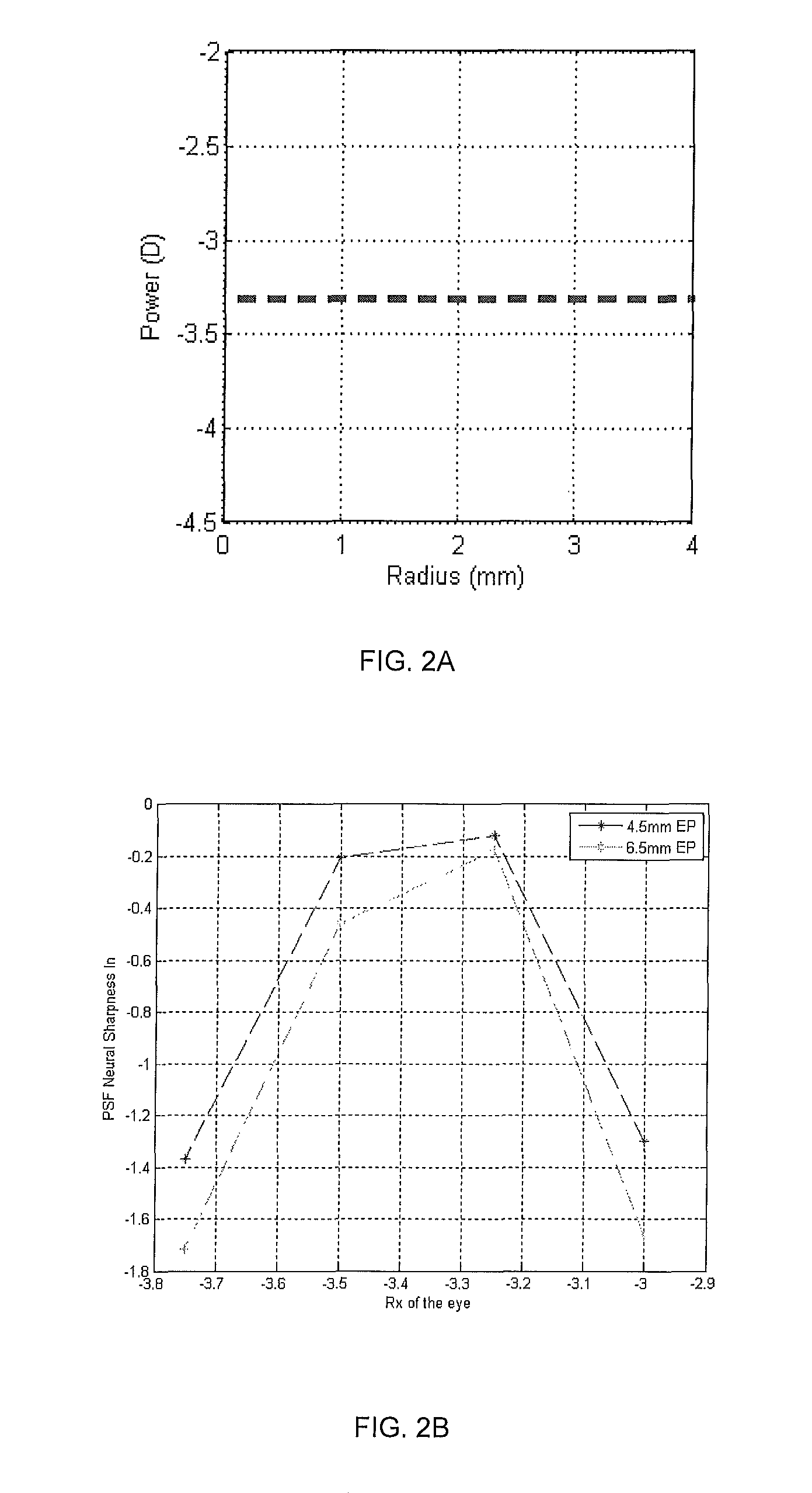
[0029]Myopes usually progress toward more severe myopia over the course of time. According to the present invention, lens designs are provided having a center and at least one peripheral zone surrounding the center and having a different dioptric power than at the center. The lens designs may have variety of power profiles including, but not limited to, spherical lenses, lenses having spherical aberration, multifocal lenses, freeform lenses, segmented freeform lenses, and the like. According to the present invention, the power profiles minimize changes in visual acuity variation, as measured by neural sharpness, over a specific period of time at a defined myopia progression rate.

[0030]According to the present invention, a myopia progression rate may be selected based at least one factor such as gender, age, ethnicity, family history, or any combination thereof. In specific embodiments, the myopia progression rate may range from about −0.25 D / year to about −0.75 D / year. Prevalence, i...


PUM


Abstract

Contact lenses incorporate power profiles that minimize visual acuity variation for progressing myopes based upon minimization of the variation of neural sharpness image quality over a specific time period. The contact lens includes a center and at least one peripheral zone surrounding the center and having a different dioptric power than at the center. The lens has power profile selected from the group consisting of a power profile with spherical aberration, a multifocal power profile, a freeform power profile, and a segmented freeform power profile. The power profile is based on an initial paraxial power of a myopia progressor and a defined myopia progression rate over a specific time period, resulting in controlled change of the neural sharpness, thereby minimizing changes in changes in visual acuity at a beginning of the time period and at an end of the time period.

Description

BACKGROUND OF THE INVENTION[0001]1. Field of the Invention[0002]The present invention relates to ophthalmic lenses. More particularly, the present invention is directed to ophthalmic lenses having power profiles that provide foveal vision correction and minimize visual acuity variation experienced by progressing myopes over the course of time.[0003]2. Discussion of the Related Art[0004]Common conditions which lead to reduced visual acuity include myopia and hyperopia, for which corrective lenses in the form of spectacles, or rigid or soft contact lenses, are prescribed. The conditions are generally described as the imbalance between the length of the eye and the focus of the optical elements of the eye, myopic eyes focusing in front of the retinal plane and hyperopic eyes focusing behind the retinal plane. Myopia typically develops because the axial length of the eye grows to be longer than the focal length of the optical components of the eye, that is, the eye grows too long. Hyper...

Claims


Application Information

Patent Timeline
Patent Type & Authority Patents(United States)
IPC IPC(8): G02C7/04A61F2/14A61F2/16G02C7/06
CPCA61F2/145A61F2/1656G02C7/041G02C7/06G02C7/044G02C2202/24A61F9/00G02C7/04
Inventor BRENNAN, NOEL A.CHEHAB, KHALED A.ROFFMAN, JEFFREY H.WEI, XIN
Owner JOHNSON & JOHNSON VISION CARE INC
Why Eureka
Try Eureka