
Ghosting compensation in relief images for directional prints

a relief image and ghosting compensation technology, applied in printing, printing processes, coatings, etc., can solve the problem of not having a method to reduce this ghosting effect, and achieve the effect of reducing the ghosting

Inactive Publication Date: 2016-08-16
OCE TECH
View PDF28 Cites 0 Cited by
  • Summary
  • Abstract
  • Description
  • Claims
  • Application Information

AI Technical Summary

Benefits of technology

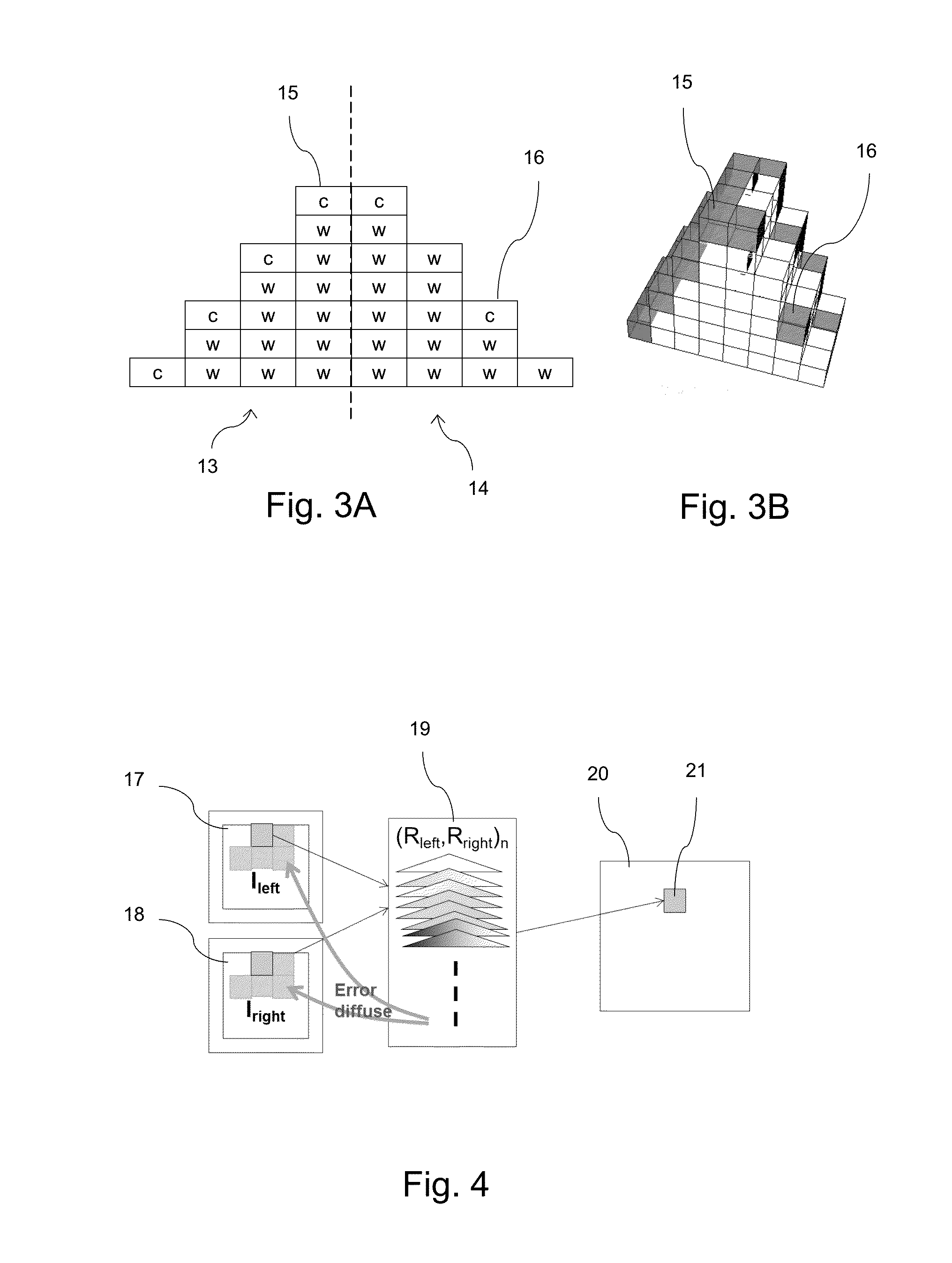
[0007]According to the present invention, a method is provided for combining two source images in a relief image with structural elements having at least two principle surface orientations, such that a first image is observed in a first viewing direction and a second image is observed in a second viewing direction, the method reducing a ghosting effect and comprising the steps of: a) printing a test relief image comprising patches with structural elements having a first basic color on a surface with a first principle orientation and a second basic color on a surface with a second principle orientation, a basic color being a color having a predefined amount of colorant; b) measuring for each patch a first observed color in a first viewing direction and a second observed color in a second viewing direction; c) scaling a first source image and a second source image such that each image element has a size corresponding to a structural element in the relief image; d) selecting for each position in the relief image a structural element from a patch in the test relief image, wherefor a sum of a color difference between an image element of the scaled first source image and a first observed color and a color difference between an image element of the scaled second source image and a second observed color becomes minimal, and e) composing a relief image from the selected structural elements. A perceived color in a first direction depends not only on the first basic color, but also on the second basic color, due to the ghosting effect. By selecting a structural element for which an observed color in its surrounding, including a color of a second image, is compared to an intended color, the ghosting effect is reduced. This is done for both images by minimizing a sum of a color difference in both directions. The resulting relief image comprises structural elements with a basic color on either side of the structural element, the basic color having a minimal color difference with the intended color of the corresponding image element at the position of the structural element in the relief image. This solves a problem for these relief images.

Problems solved by technology

A problem of the current state of the art is that no method exists to reduce this ghosting effect.

Method used


Image

  • Ghosting compensation in relief images for directional prints
  • Ghosting compensation in relief images for directional prints
  • Ghosting compensation in relief images for directional prints

Examples


Embodiment Construction

[0016]The present invention will now be described with reference to the accompanying drawings, wherein the same or similar elements are identified with the same reference numeral.

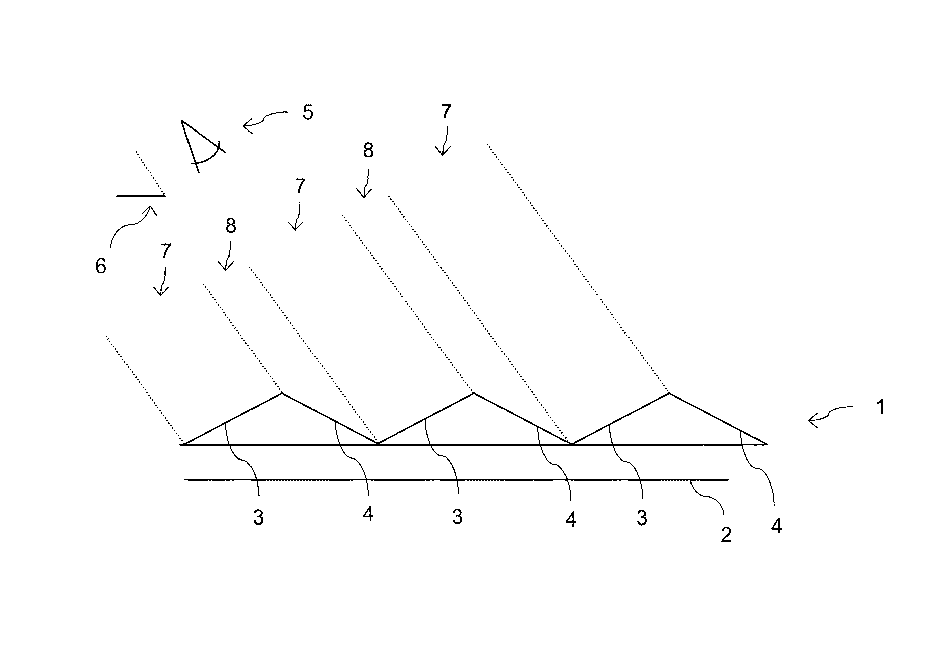
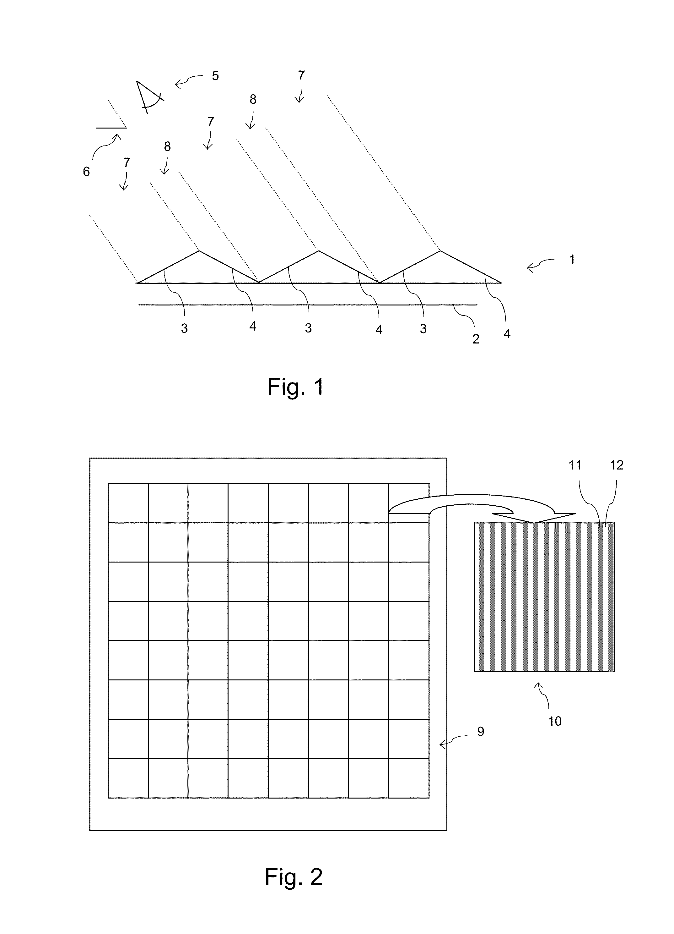
[0017]FIG. 1 shows a profile of a relief print with structural elements 1 on a flat substrate 2. The structural elements have each two principle surface orientations, one, surface 3, directed to the left side and one, surface 4, directed to the right side in the figure. A relief print is obtained by applying a varying amount of ink dots on top of each other as defined in a relief image that comprises a separate channel for indicating a height or elevation for each pixel in the image besides the customary channels for indicating a color or an amount of colorant for each pixel. The profile in FIG. 1 is obtained by increasing the height for a number of consecutive pixels and decreasing the height for a next number of consecutive pixels, as will be further illustrated in a next figure.

[0018]Observing the relief...


PUM


Abstract

A method is provided for combining two source images in a relief image. Structural elements are applied that allow a first image to be observed in a first viewing direction and a second image in a second viewing direction. The method reduces a ghosting effect by a) printing a test relief image wherein the two source images comprise patches with a number of basic colors having a predefined amount of colorant; b) measuring for each patch an observed color in each of the viewing directions; c) scaling the source images such that an image element matches a size of a structural element in the relief image; d) selecting a structural element from the test relief image, wherefore the color differences between the image elements of the scaled source images and the patch color becomes minimal, and e) composing a relief image from the selected structural elements.

Description

BACKGROND OF THE INVENTION[0001]1. Field of the Invention[0002]Color printers are available for printing many different kind of images, such as text documents and digital photographs, in all imaginable sizes. Most of these images are two-dimensional in nature and the extension of the colorants in a third dimension is usually very limited. Still, relief images are known, wherein multiple colorant layers are printed onto each other on a flat substrate, thereby obtaining an elevated surface. Also, three-dimensional printers for producing objects of arbitrary shape have become ubiquitous in recent years, using many different materials than the usual inks and toners of traditional color printers. The availability of all these printers has triggered creativity for developing image processing methods that enable a printer to produce new types of prints. The present invention relates to a method for combining two source images in a relief image with structural elements having at least two p...

Claims


Application Information

Patent Timeline
Patent Type & Authority Patents(United States)
IPC IPC(8): G06K15/02H04N1/60B05D5/06B41M3/00
CPCG06K15/1878G06K15/027H04N1/60B05D5/06B41M3/00H04N1/605
Inventor BAAR, TEUN R.SHAHPASKI, MARJANORTIZ SEGOVIA, MARIA V.
Owner OCE TECH
Learn More