Unlock instant, AI-driven research and patent intelligence for your innovation.

Display control device, display control method, non-transitory computer-readable recording medium, and projecting device

a technology of display control and projecting device, which is applied in the direction of static indicating device, road vehicle traffic control, instruments, etc., can solve problems such as visibility problems, and achieve the effect of improving the visibility of speed limit information

Active Publication Date: 2016-08-16
PANASONIC INTELLECTUAL PROPERTY MANAGEMENT CO LTD
View PDF8 Cites 0 Cited by
  • Summary
  • Abstract
  • Description
  • Claims
  • Application Information

AI Technical Summary

Benefits of technology

Improves the visibility of speed limit information by ensuring clear and unobtrusive transitions between speed limits, enhancing driver awareness and reducing visual disturbance.

Problems solved by technology

However, the related art has been problematic in the visibility of the speed limit information at the time of a switchover on the display medium between images indicating a speed limit.

Method used


Image

  • Display control device, display control method, non-transitory computer-readable recording medium, and projecting device
  • Display control device, display control method, non-transitory computer-readable recording medium, and projecting device
  • Display control device, display control method, non-transitory computer-readable recording medium, and projecting device

Examples


first embodiment

[0035]A first embodiment of the present disclosure will be described with reference to the drawings.

[0036]First, an example of the structure of a display system 1 according to this embodiment will be described with reference to FIG. 1. FIG. 1 is a block diagram illustrating an example of the structure of the display system 1 according to this embodiment.

[0037]The display system 1 is used in, for example, a moving body such a vehicle to assist the operation of the vehicle. The display system 1 may be a vehicle-mounted device or a device that is brought in a vehicle. Although, in this embodiment, an example in which the user is an occupant in a vehicle, particularly, the driver of the vehicle will be described, this is not a limitation. In addition, the display system 1 may be used in a wearable computer (for example, a head-mounted display or helmet-mounted display (HMD), which will be described later, that the user can wear on the user's body.

[0038]In FIG. 1, the display system 1 in...

first specific example

[0136]The first specific example will be described with reference to FIGS. 13A and 13B. FIG. 13A illustrates a specific example in which control is switched in the first switching method. FIG. 13B illustrates a specific example in which control is switched in the second switching method.

[0137]First, a specific example in which control is switched in the first switching method will be described with reference to FIG. 13A.

[0138]During time T1, the controller 201 controls the displayer 30 so that it creates the first predetermined image, which represents the first visual image 101 when the first predetermined image is displayed on the display medium, and displays the first predetermined image on the display medium at a first brightness B1. Thus, the first visual image 101 is displayed on the display medium.

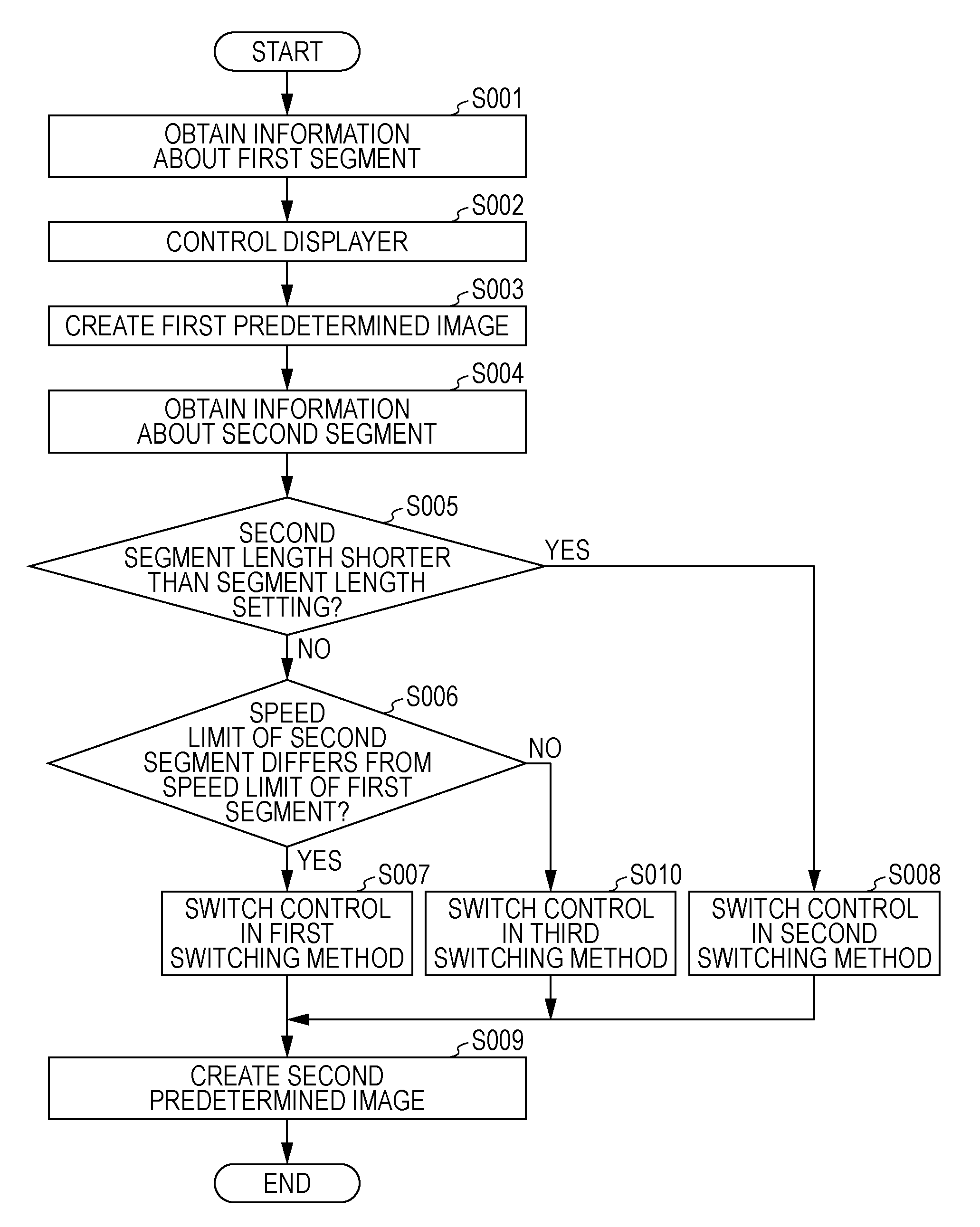
[0139]Then, when the vehicle enters the road link L2, if the determiner 202 determines that the second-segment length is not shorter than the segment length setting and that the spee...

second specific example

[0150]The second specific example will be described with reference to FIGS. 14A and 14B. FIG. 14A illustrates a specific example in which control is switched in the first switching method. FIG. 14B illustrates a specific example in which control is switched in the second switching method.

[0151]First, a specific example in which control is switched in the first switching method will be described with reference to FIG. 14A.

[0152]During time T1, the controller 201 controls the displayer 30 so that it creates the first predetermined image, which represents the first visual image 101 when the first predetermined image is displayed on the display medium, and displays the first predetermined image on the display medium at the first brightness B1. Thus, the first visual image 101 is displayed on the display medium.

[0153]Then, when the vehicle enters the road link L2, if the determiner 202 determines that the second-segment length is not shorter than the segment length setting and that the s...


PUM


Abstract

A display control device includes a controller that, if an obtainer obtains first-segment speed limit information, controls a displayer so that it creates a first predetermined image, indicating a first-segment speed limit, and displays the first predetermined image on a display medium, and includes a determiner that, if second-segment length information is obtained after the first-segment speed limit information has been obtained, determines whether the second-segment length is shorter than a threshold. The controller makes a switchover from control under which the displayer creates the first predetermined image and displays it on the display medium to control under which the displayer creates a second predetermined image, indicating a second-segment speed limit, and displays the second predetermined image on the display medium in different control ways depending on whether the second-segment length is shorter than the threshold.

Description

BACKGROUND[0001]1. Technical Field[0002]The present disclosure relates to a display control device, a display control method, a non-transitory computer-readable recording medium, and a projecting device that control the displaying of information provided to an occupant in a vehicle or the like.[0003]2. Description of the Related Art[0004]In recent years, the development of a driving assistance system has been pursued in which an image of a road sign or the like is obtained by a vehicle-mounted camera, information about the speed limit of the road on which the vehicle is travelling is obtained from the image, and an occupant is notified of the obtained speed limit information to prevent the speed limit from being exceeded. This type of drive assistance system is disclosed in, for example, Japanese Unexamined Patent Application Publication No. 2009-187166 (the drive assistance system will be referred to below as the related art).[0005]In the related art, the speed limit of the lane on...

Claims


Application Information

Patent Timeline
Patent Type & Authority Patents(United States)
IPC IPC(8): G08G1/0967G09G3/04G08G1/0962
CPCG08G1/0967G08G1/0962G08G1/09675G09G3/04B60R2300/80
Inventor OHDACHI, ERIKOEMURA, KOICHIMOCHIZUKI, MAKOTO
Owner PANASONIC INTELLECTUAL PROPERTY MANAGEMENT CO LTD