Method for forming shaped label stacks

a technology of shaped labels and stack packs, applied in the direction of metal working devices, etc., can solve the problems of increasing the dwell time of the knife until the settling of the knife, the deformation of the knife, and the reduction of the cutting quality with increasing operating frequency, so as to achieve the effect of increasing outpu

Active Publication Date: 2016-08-23
BLUMER MASCHENBAU
View PDF30 Cites 4 Cited by
  • Summary
  • Abstract
  • Description
  • Claims
  • Application Information

AI Technical Summary

Benefits of technology

[0011]As a result, it is one object of this invention, to provide a method, by way of which known installations for forming shaped label stack packs can have their output increased, without a significant cost increase of the known installation.

Problems solved by technology

Thus, one has ascertained that when increasing the frequency of the die-cutting device, the penetration speed which also increases as a consequence, leads to a greater deformation of the knife and the cutting quality thus reduces with an increasing operating frequency and subsequently the dwell time until the settling of the knife increases due to the increasingly occurring oscillations.
This results in the dilemma of the output performance of an installation for forming shaped label stack packs not able to be simply increased by way of forming more stack packs per time unit, but one would simultaneously have to succeed in the cycle time of the die-cutting device being able to be reduced.

Method used


Image

  • Method for forming shaped label stacks
  • Method for forming shaped label stacks
  • Method for forming shaped label stacks

Examples


Embodiment Construction

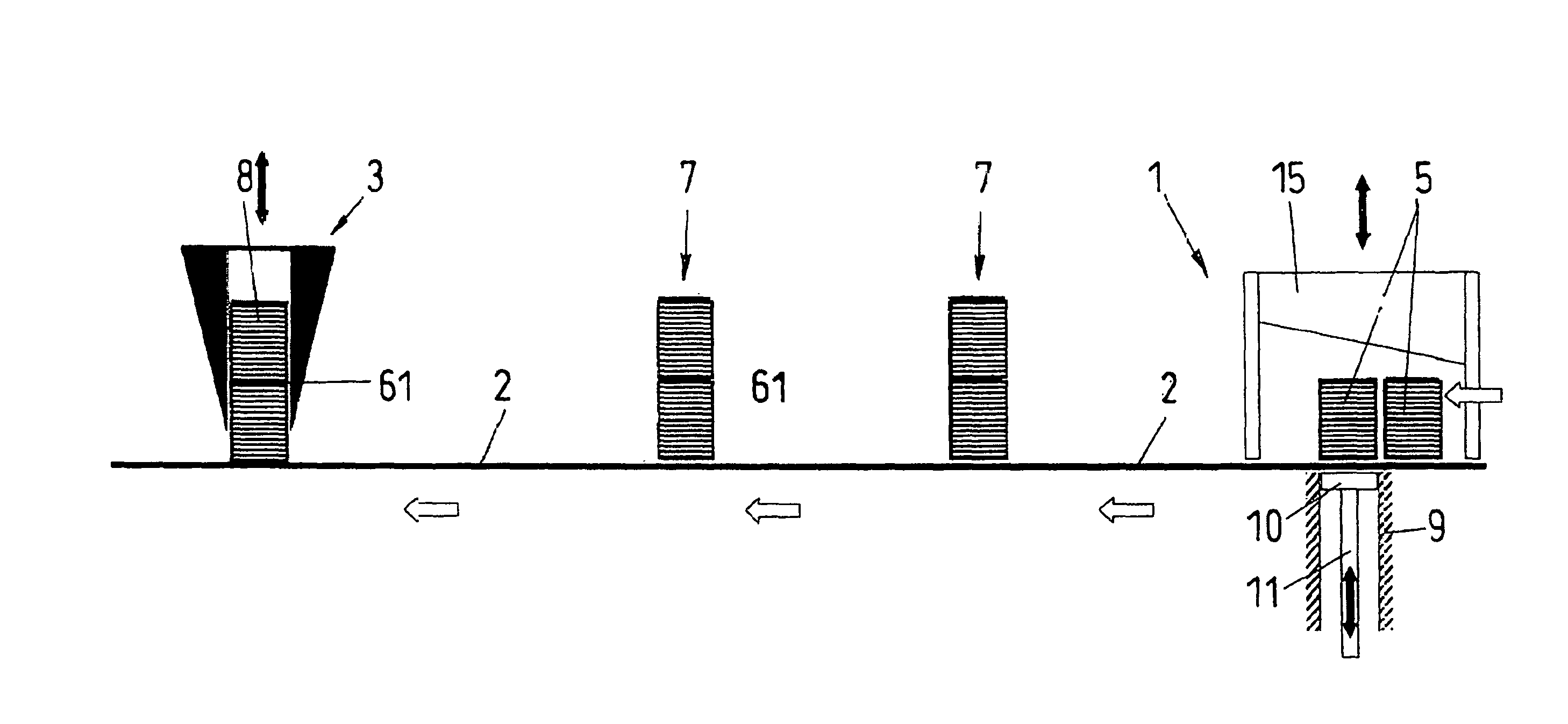
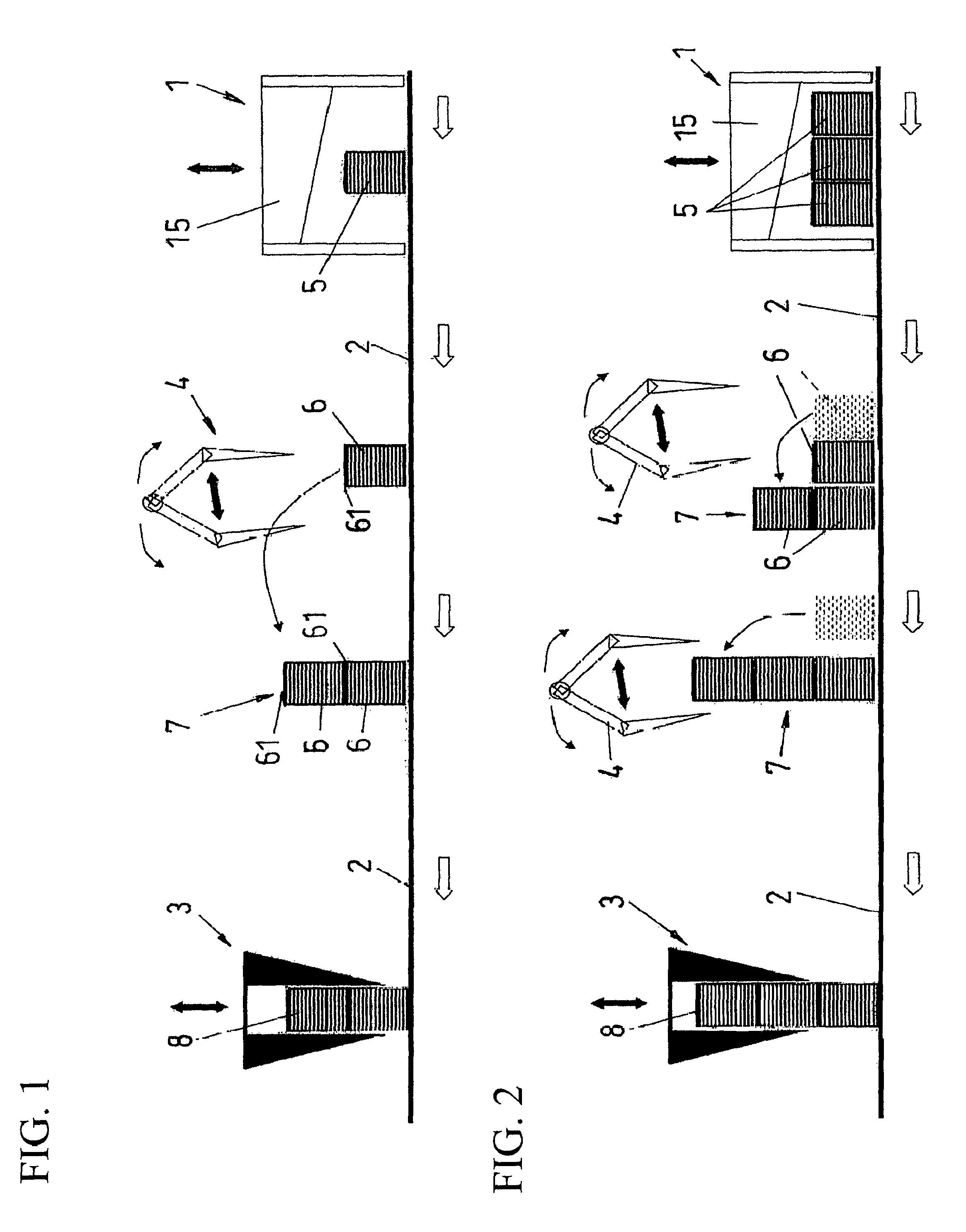
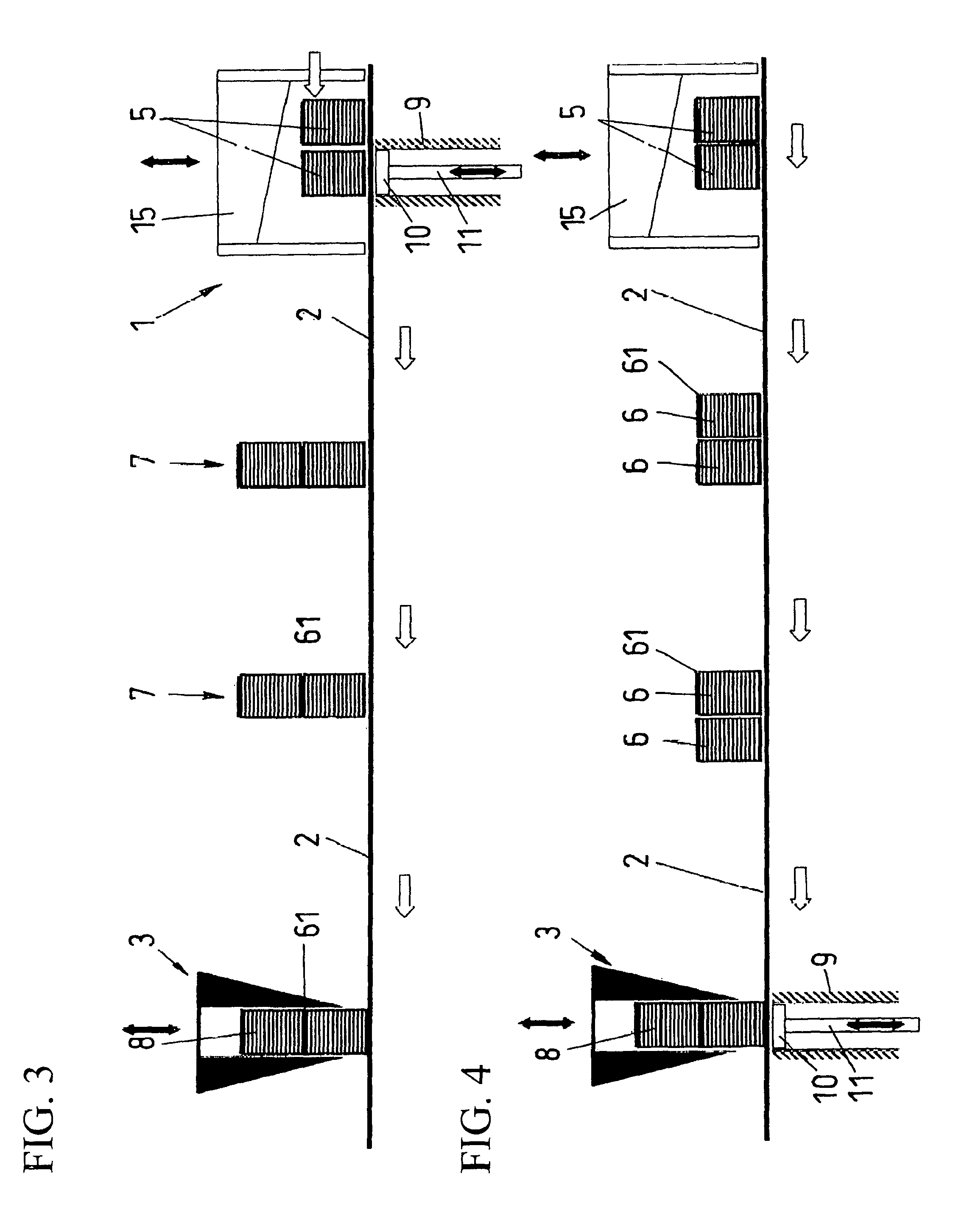
[0017]A first embodiment of the method according to this invention is shown in FIG. 1. The method takes its course from the right to the left in the drawing. Accordingly, at the far right the symbolically represented strip pack cross-cutter is indicated as element reference numeral 1. The transfer or conveying section 2 extends from the strip pack cross-cutter 1 up to the die-cutting device 3. A gripper 4 is symbolically represented between the strip pack cross-cutter 1 and the die-cutting device 3. The strip packs 5 cut from sheets are present at the strip packet cross-cutter 1. The strip pack 5 is represented with a view to the narrow face side. The knife 15 of the strip pack cross-cutter in a stepped manner separates pieces from this, according to the size of the shaped labels to be formed, and these cut away pieces are indicated as stack packs. The stack pack has the reference numeral 6. The transfer or conveying section 2 is shown in a level manner in the installation represent...


PUM

PropertyMeasurementUnit
heightaaaaaaaaaa
timeaaaaaaaaaa
distanceaaaaaaaaaa

Abstract

A method for shortening the processing time on creating shaped label stacks. Between a strip pack cross-cutter and a die-cutting device in the region of a conveying section, the strip packs cut by way of the strip pack cross-cutter into stack packs are transferred and then die-cut in the die-cutting device into shaped label stacks. Two or more stack packs are layered on one another in the region of the conveying section and the layered stack packs are die-cut into shaped label stacks, for increasing the die-cutting output. The layered, die-cut stacks can then be divided again into shaped label stacks that can be managed and banded.

Description

BACKGROUND OF THE INVENTION[0001]1. Field of the Invention[0002]This invention relates to a method for forming shaped label stack packs using a strip pack cross-cutter and a die-cutting device, between which a conveying section is present, wherein a multitude of printed strips which are pre-cut in strips from the sheet form a strip pack which is cut on the strip pack cross-cutter into stack packs and led to the die-cutting device, upon which the stack packs are die-cut into shaped label stack packs.[0003]2. Discussion of Related Art[0004]Parts of such an installation which are suitable for carrying out the method according to this invention are known from various documents. In their entirety, such installations on the market are also offered by the applicant. European Patent Reference EP 482435 shows a conveying section or transfer section and a subsequent die-cutting device which is additionally equipped with a banding station. The strip pack cross-cutter, not represented in the do...

Claims


Application Information

Patent Timeline
Patent Type & Authority Patents(United States)
IPC IPC(8): B26F1/14B26F1/40B26D7/06B26D11/00
CPCB26D7/0675B26F1/40B26F1/14B65H2301/4224B65H2301/4229Y10T83/0505B26D2011/005
Inventor BAECHTOLD, GEORGESAMHERD, RENE
Owner BLUMER MASCHENBAU
Why Eureka
Try Eureka