Over-center handle mechanism for increased tactile feedback on a rotary actuator

a technology of rotary actuator and over-center handle, which is applied in the direction of mechanical control devices, protection switch operating/releasing mechanisms, instruments, etc., can solve the problems of poor matching of angular torque characteristics of through-door handles, and achieve the effect of optimizing angular torque or snapping “feeling”, reducing friction, and increasing tactile feedback

Active Publication Date: 2016-08-23
SCHNEIDER ELECTRIC USA INC
View PDF4 Cites 3 Cited by
  • Summary
  • Abstract
  • Description
  • Claims
  • Application Information

AI Technical Summary

Benefits of technology

[0004]An improved over-center handle mechanism is provided for operating electrical equipment, such as an electrical switch or circuit breaker, housed in an electrical enclosure using a through-door handle from outside of the electrical enclosure. For example, the over-center handle mechanism can include an adaptor knob, a rotary actuator and a through-door handle (e.g., an external handle on the exterior of an electrical enclosure). The adaptor knob interfaces with the electrical equipment. For example, the adaptor knob can include an aperture configured to slide over a circuit breaker or switch handle. The rotary actuator is connected to the adaptor knob and includes a cam. The through-door handle is used to operate the rotary actuator, which in turn operates the electrical equipment via the adaptor knob. To optimize an angular torque or snap “feeling” at the through-door handle, the over-center handle mechanism further includes a spring to provide an opposing force against movement of the cam of the rotary actuator, and thus, the through-door handle when operating the electrical equipment to different positions (e.g., OFF or ON position). A solid lubricant of PTFE can be provided as an interface between the cam and the spring to reduce friction therebetween. Accordingly, the over-center handle mechanism is able to provide for increased tactile feedback on the rotary actuator, and thus, the through-door handle. Furthermore, the over-center handle mechanism can be configured with a smaller form factor and minimized part count.

Problems solved by technology

Since the electrical equipment may not be originally designed specifically for operation with the through-door handle, the angular torque characteristics of the through-door handle may be poorly matched tier operating the electrical equipment that is housed in the electrical enclosure.

Method used


Image

  • Over-center handle mechanism for increased tactile feedback on a rotary actuator
  • Over-center handle mechanism for increased tactile feedback on a rotary actuator
  • Over-center handle mechanism for increased tactile feedback on a rotary actuator

Examples


Embodiment Construction

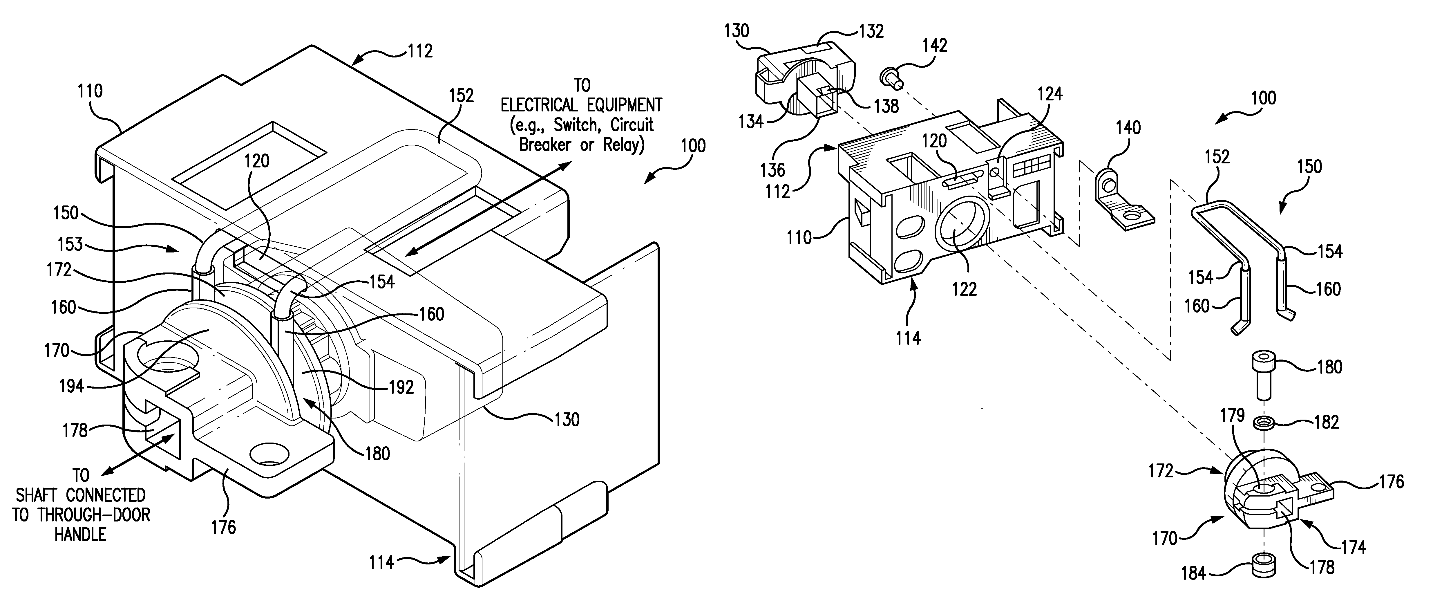
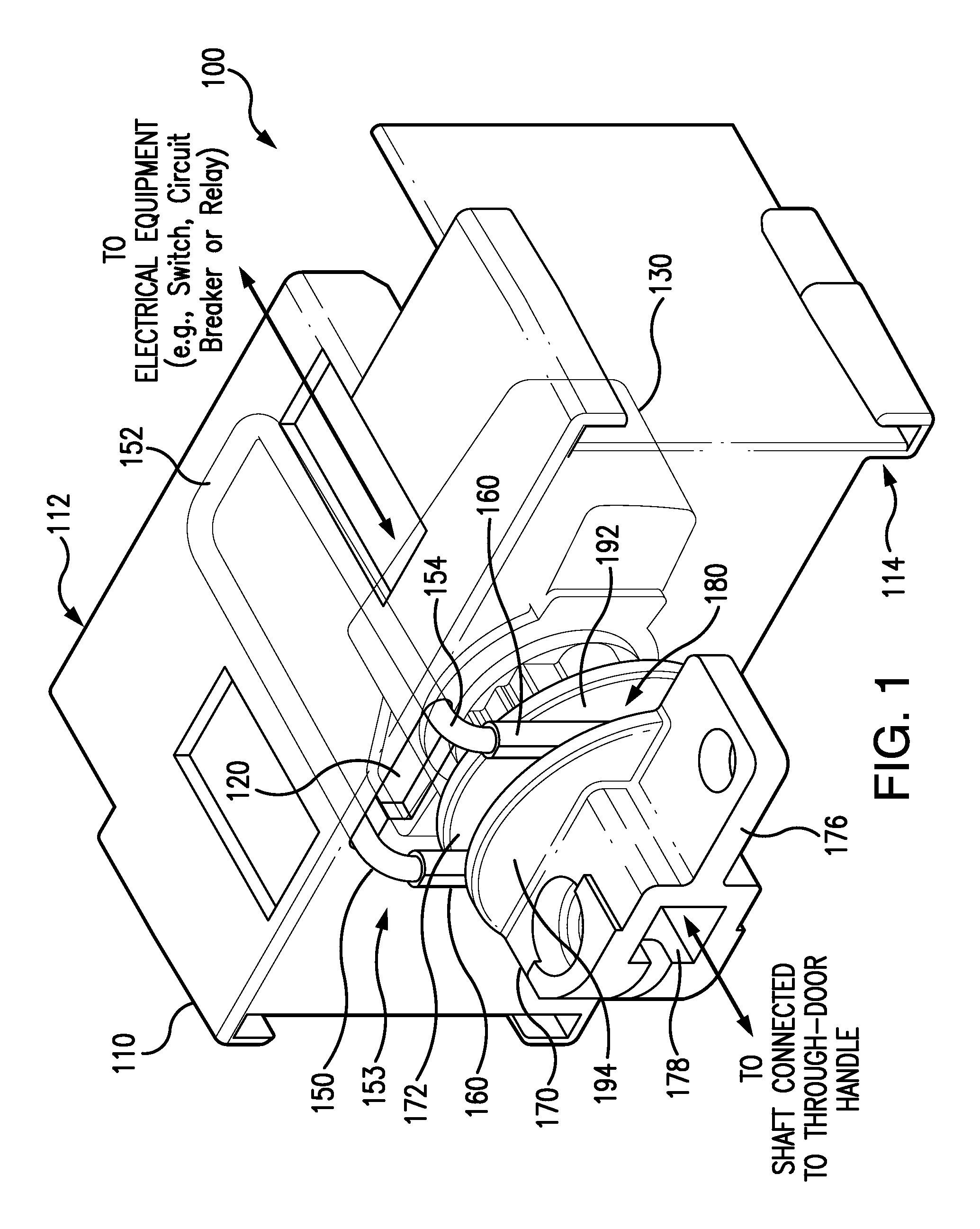
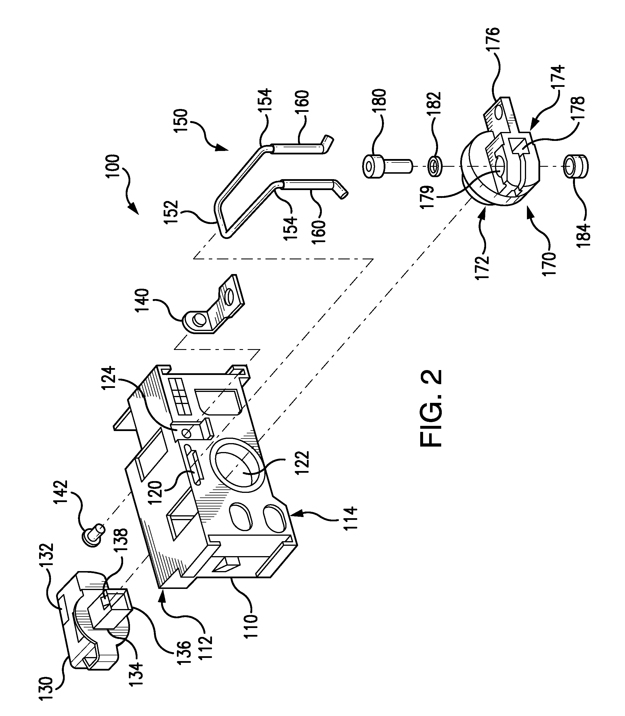
[0015]The present disclosure describes an over-center handle mechanism 100 for operating electrical equipment (e.g., an electrical switch, a circuit breaker or relay) housed in an electrical enclosure. The over-center handle mechanism 100 includes an adaptor knob 130 to interface with the electrical equipment, a rotary actuator 170 connected to the adaptor knob 130, and a spring 150. A through-door handle, which is outside of the enclosure, is operatively connected to the rotary actuator 170 to operate the electrical equipment, via the rotary actuator 170 and the adaptor knob 130. The spring 150 is arranged to apply an opposing force (e.g., a spring force) against an outer cam surface of a cam 300 on the rotary actuator 170 to adjust and control an angular torque characteristic of the rotary actuator 170, and thus, the through-door handle connected thereto. An example of the over-center handle mechanism 100 is described in greater detail below with reference to the figures.

[0016]FIG...


PUM


Abstract

An over-center handle mechanism is provided to operate electrical equipment, such as a switch or breaker, housed in an electrical enclosure. The over-center handle mechanism includes an adaptor knob, a rotary actuator and a spring. The adaptor knob interfaces with the electrical equipment. The rotary actuator is connected to the adaptor knob, and includes a cam. A through-door handle is used to operate the rotary actuator, which in turn operates the electrical equipment via the adaptor knob. To optimize an angular torque feeling at the through-door handle, the over-center handle mechanism further includes the spring to provide an opposing force against movement of the cam of the rotary actuator, and thus, the through-door handle. A solid lubricant of PTFE may also be provided as an interface between the cam and the spring to reduce friction therebetween.

Description

RELATED CASES[0001]The present application claims priority under 35 U.S.C. §119(e) based on U.S. Provisional Application Ser. No. 61 / 935,544 filed on Feb. 4, 2014, which is incorporated by reference herein in its entirety.FIELD[0002]The present disclosure is related to an over center handle mechanism with a rotary actuator for operating electrical equipment housed in an electrical enclosure, and more particularly, to a spring assembly to adjust and control angular torque characteristic of the rotary actuator of an over-center handle mechanism.BACKGROUND[0003]There are many kinds of electrical equipment that, for safety considerations, are located inside an electrical enclosure and operated using a through-door handle with appropriate linkage to the equipment. For ergonomic reasons, electrical enclosures are often equipped with a large through-door handle to operate the electrical equipment, which can include for example a. circuit breaker(s), an electrical switch(es) or components t...

Claims


Application Information

Patent Timeline
Patent Type & Authority Patents(United States)
IPC IPC(8): H01H21/40H01H71/56G05G1/10G05G5/03
CPCG05G1/10G05G5/03H01H71/56Y10T74/20474G05G5/06
Inventor GIBBONS, JR., DONALD G.ROBBINS, TONY R.EDWARDS, JR., STANLEY H.
Owner SCHNEIDER ELECTRIC USA INC
Why Eureka
Try Eureka