Arrangement for moving a movable furniture part

a technology for moving furniture and furniture parts, applied in the direction of mechanical controls, applications, door/window fittings, etc., can solve the problems of occupying a large space, affecting the aesthetics of the room,

Active Publication Date: 2016-08-30
JULIUS BLUM GMBH
View PDF27 Cites 8 Cited by
  • Summary
  • Abstract
  • Description
  • Claims
  • Application Information

AI Technical Summary

Benefits of technology

[0004]The object of the present invention is to avoid the above-described disadvantages and to provide an improved arrangement for moving a moveable furniture part.
[0007]What is advantageous in regard to the use of a Bowden cable in connection with the subject of the present invention is that it takes up relatively little space and can be flexibly laid. It is also possible for it to be “concealed”, for example, in a groove or the like in relation to the exterior.
[0008]In an advantageous embodiment of the invention, the loading device includes at least one adjusting body and at least one adjusting contour. The at least one adjusting body runs against the at least one adjusting contour at least during a part of the opening or closing movement. Different kinematic conditions can be achieved by the interplay of the at least one adjusting body and the at least one adjusting contour. In particular, it is also possible to implement a neutral region in which the at least one adjusting body and the at least one adjusting contour move relative to each other in such a way that the at least one force storage element is not loaded. A further great advantage arising out of the interplay of the at least one adjusting body and the at least one adjusting contour is the fact that the transitions between loading and non-loading of the force storage element can be of a very smooth and gentle nature.

Problems solved by technology

They have relatively complicated and expensive transmission mechanisms disposed between the at least one ejection device and the loading device for the transmission of force upon loading of the at least one force storage element.
Thus, for example, direction-changing devices or intermediate panels are required, which take up a very great deal of space.
That is also disadvantageous from esthetic points of view.

Method used


Image

  • Arrangement for moving a movable furniture part
  • Arrangement for moving a movable furniture part
  • Arrangement for moving a movable furniture part

Examples


Embodiment Construction

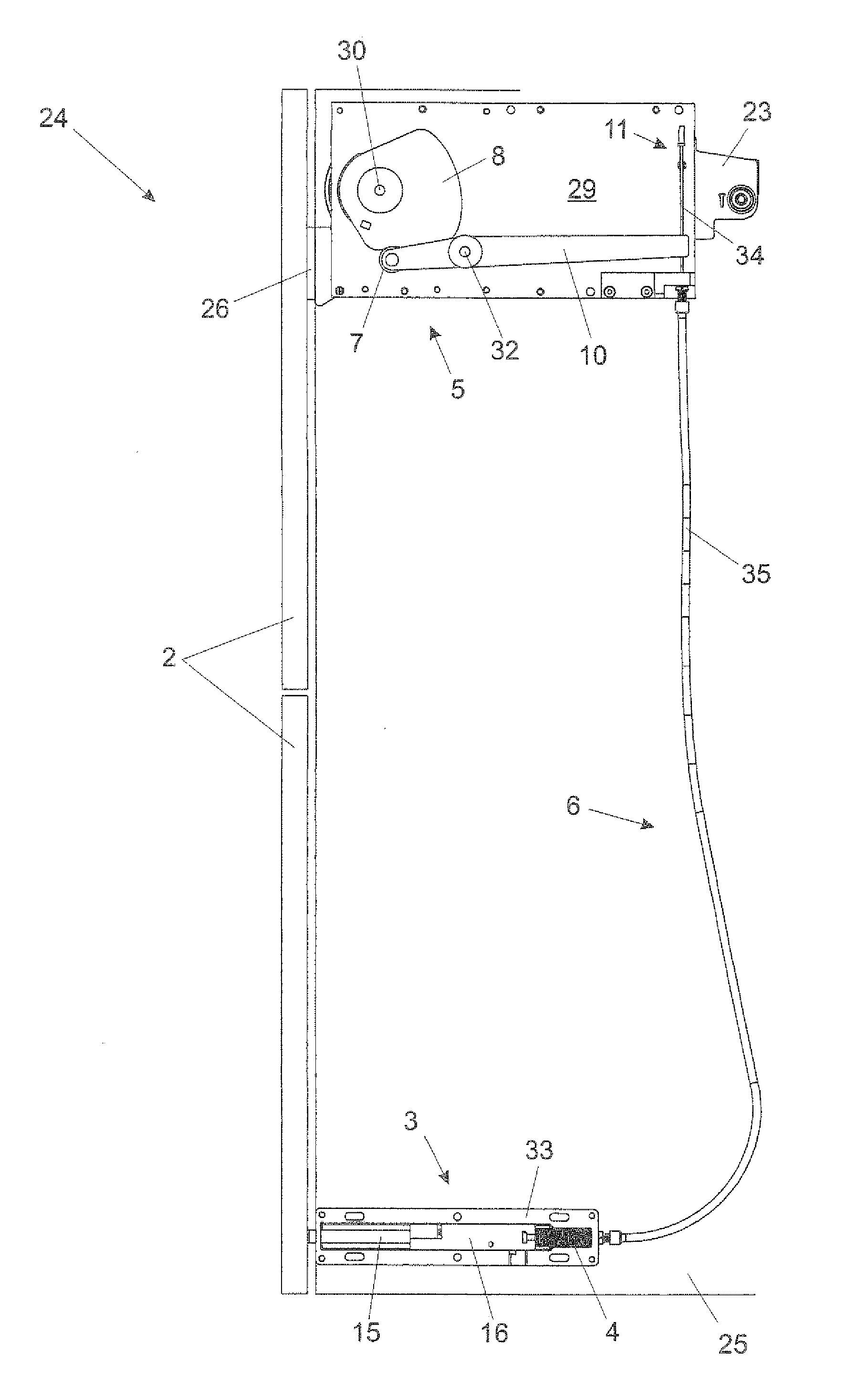
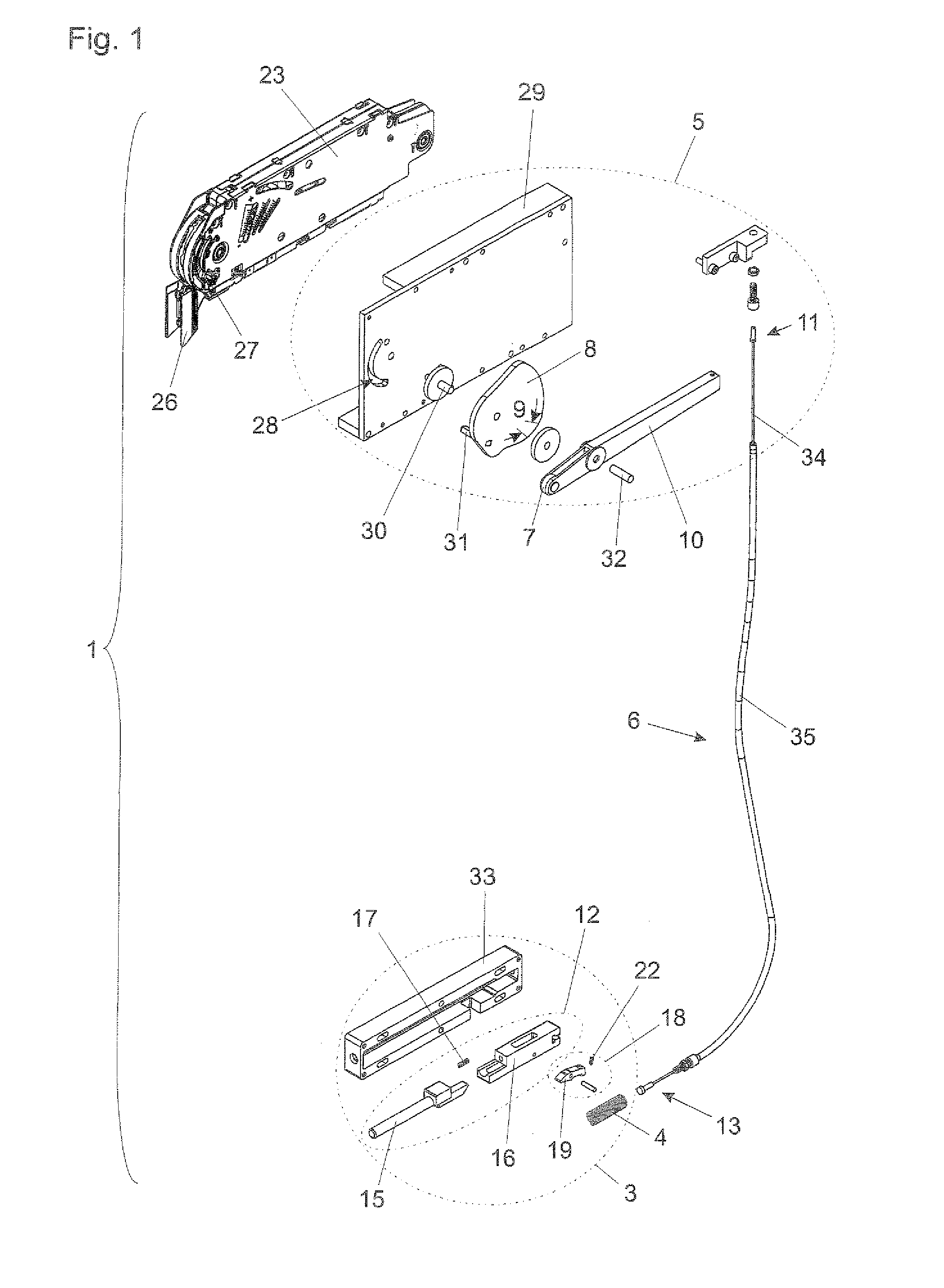
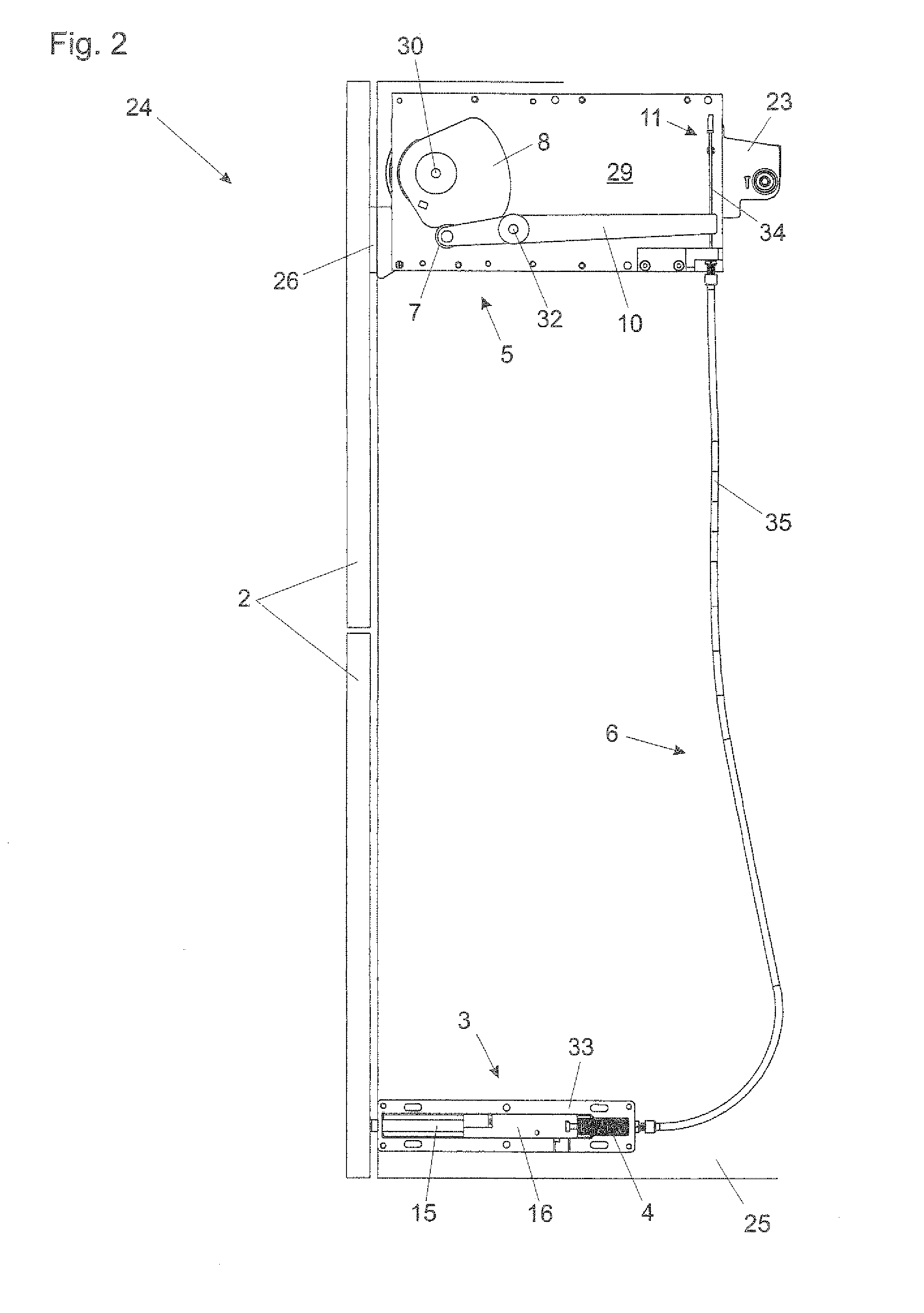
[0016]With reference to the exploded view shown in FIG. 1 it can be seen that the ejection device 3 of the arrangement 1 includes an ejection element 12 which is moveable, more precisely linearly displaceable, and which can be acted upon by a force storage element 4 in the form of a spring. The ejection element 12 has two parts 15 and 16 which are moveable relative to each other over a limited distance 14 (see FIGS. 7a through 7e), and a compression spring 17 is arranged between the two parts 15 and 16. The ejection element 12 is arranged linearly displaceably in a parallelepipedic housing 33. A further substantial component of the ejection device 3 is a locking device 18 for releasably locking the ejection element 12 in relation to being acted upon by the force storage element 4, and the locking device 18 is releasable by over-pressing in opposition to the ejection direction. The core element of the locking device 18 is a tilting lever 19. On one arm, the tilting lever 19 has a lat...


PUM


Abstract

An arrangement for moving a movable furniture part, in particular a furniture part which is mounted pivotably about an axis, includes at least one ejection device for ejecting the movable furniture part from a closed position into an open position, and the at least one ejection device includes at least one force accumulator. The arrangement further includes a loading device for loading the at least one force accumulator by an opening or closing movement of the movable furniture part. At least one Bowden cable for transmitting force during the loading of the at least one force accumulator is arranged between the at least one ejection device and the loading device.

Description

BACKGROUND OF THE INVENTION[0001]The invention concerns an arrangement for moving a moveable furniture part, in particular a furniture part mounted pivotably about an axis. The arrangement includes at least one ejection device for ejecting the moveable furniture part from a closed position into an open position, and the at least one ejection device includes at least one force storage element. A loading device loads the at least one force storage element by an opening or closing movement of the moveable furniture part.[0002]Such arrangements are known from application number A 322 / 2012 to the present applicant which is of an earlier priority date but which has not yet been published. They have relatively complicated and expensive transmission mechanisms disposed between the at least one ejection device and the loading device for the transmission of force upon loading of the at least one force storage element. Thus, for example, direction-changing devices or intermediate panels are re...

Claims


Application Information

Patent Timeline
Patent Type & Authority Patents(United States)
IPC IPC(8): A47B95/00E05F1/12E05B53/00E05F1/10E05D15/26E05C19/02
CPCE05B53/005E05D15/264E05F1/105E05F1/1261E05D15/262E05C19/022E05Y2201/426E05Y2201/638E05Y2201/654E05Y2900/20
Inventor BRAUNGART, HANSJOERG
Owner JULIUS BLUM GMBH
Why Eureka
Try Eureka