Eureka AIR delivers breakthrough ideas for toughest innovation challenges, trusted by R&D personnel around the world.

Method and computer system for characterizing a sheet metal part

a technology of computer system and sheet metal, applied in the field of forming processes, can solve the problems of inability to guarantee the performance of the simulation results, the cost and time-consuming of trial and error procedures, and the inability to use simulation results, etc., to achieve the effect of improving the online performance of the system and facilitating the online use of the system

Active Publication Date: 2016-08-30
NETABTAL MASCHEN
View PDF5 Cites 0 Cited by
  • Summary
  • Abstract
  • Description
  • Claims
  • Application Information

AI Technical Summary

Benefits of technology

[0025]The method is useful for guiding tool tryouts towards achieving acceptable part quality. Further, it is useful during production to assist quality control, as it provides the capability to identify defects on each part as well as feedback to operators or equipment in order to return a process that drifts away from acceptable limits back under control.
[0027]In order to facilitate the online use of the system, it is useful to calculate classes within the material flow metric. Classes can be extracted using methods such as the principal components analysis, further clustering methods or other methods that identify patterns within a population. The use of classes improves the online performance of the system, by matching the actual distribution first to a class and then to an individual simulation within that class. Alternatively or in addition, mapping functions are established between the material flow metric and the process parameters and state variables. These are surrogate models that can be represented by either a set of global mapping functions for the whole set of simulations or a class-specific set of mapping functions for each individual class. These functions are also stored for later use.

Problems solved by technology

They are then deployed to the actual production line where unfortunately their performance cannot be guaranteed as measurements are difficult or impossible and the forming process is usually poorly monitored.
Inevitably, due to common cause (non-assignable, noise) and special cause (assignable) variation and approximations between the computer simulation and the actual tools and processes, the actual parts may not be identical to the simulated part.
Currently, simulation results are typically only used little, or not at all for reference and consultation during tryouts and production.
1. When using draw-in maps during tryout, it is not possible to determine how to adjust process parameters in order to achieve the desired draw-in from the simulation. The adjustment for the different parameters is determined empirically by varying them using a best-guess method. This trial and error procedure is costly and time consuming.
2. During production, as opposed to the tryout phase, the actual draw-in is not monitored and compared against the simulated one. Process parameters, stress, strain, thickness distributions or other important quality and process control measures are also difficult to acquire and often neglected. A process can drift out of control without noticing and defective parts can end up in the assembly line.
The following references are related to this problem, but do not provide an adequate solution:
The paper concludes that it was not possible to reach a perfect match between the optimised restraining force and the actual restraining force in the tool with this method.
The method cannot be used for quality control during production.
It is not possible to identify particular defects, their location and severity.
Finally it cannot be used during try-outs.
However, the method cannot identify defects other than mismatches between CAD geometry and actual part.
Further, it does not use the simulation to provide feedback about process conditions as there is no link between the process and the stochastic simulation.
Finally, the method, if implemented, could have limited use in quality control as it cannot identify defects other than geometry divergence whereas excessive thinning and cracks, wrinkles and surface defects may be equally or more interesting.

Method used


Image

  • Method and computer system for characterizing a sheet metal part
  • Method and computer system for characterizing a sheet metal part
  • Method and computer system for characterizing a sheet metal part

Examples


Embodiment Construction

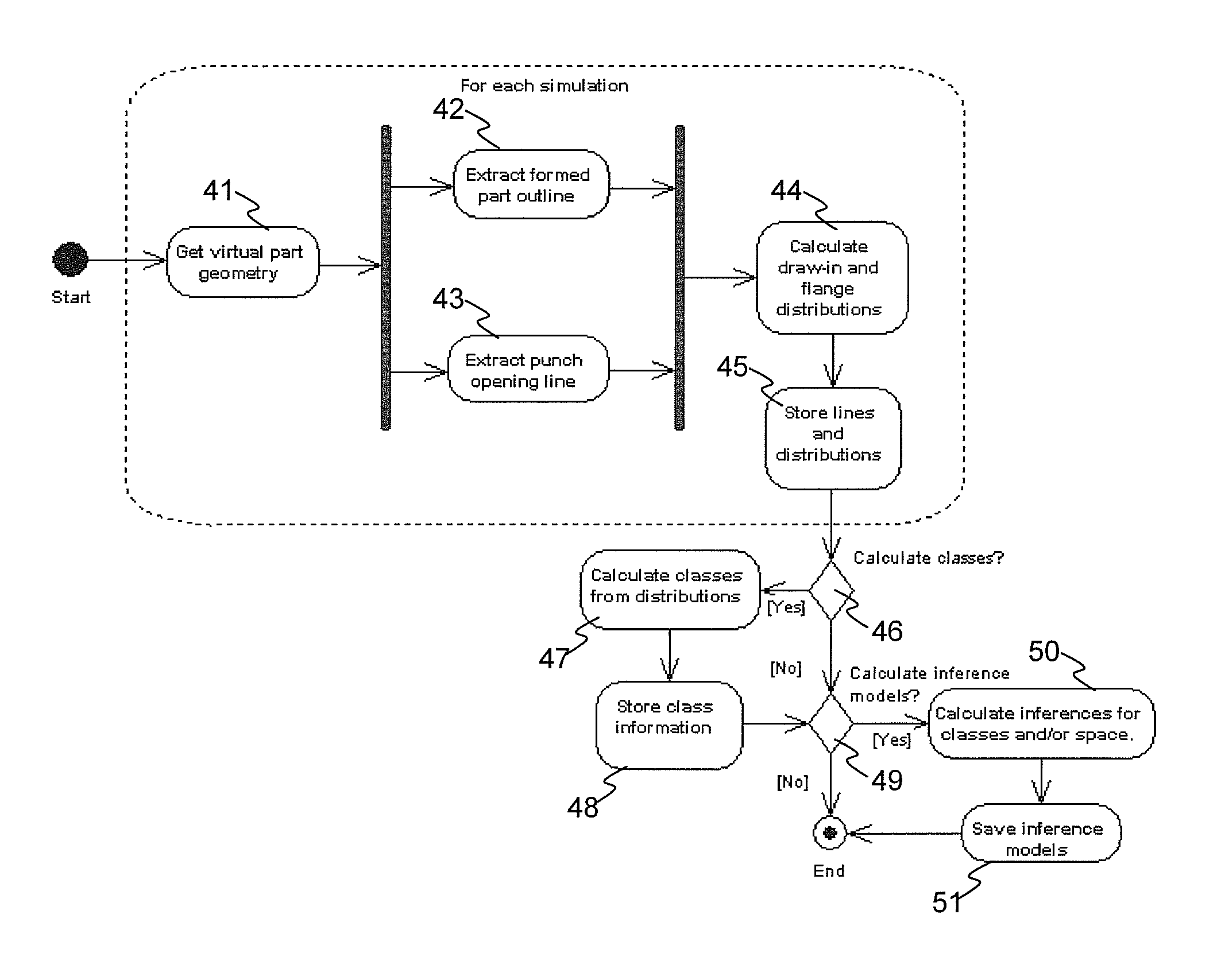
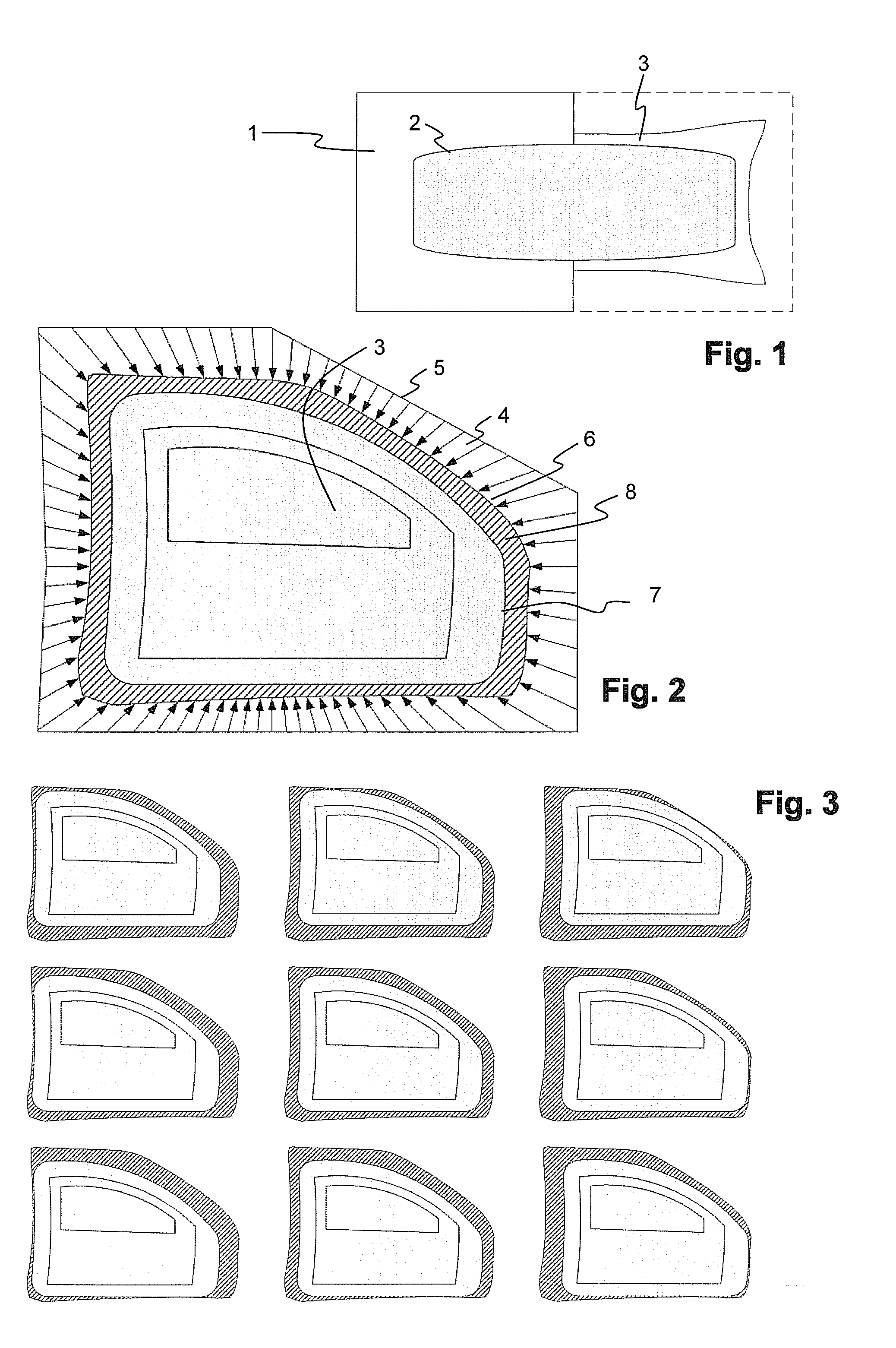
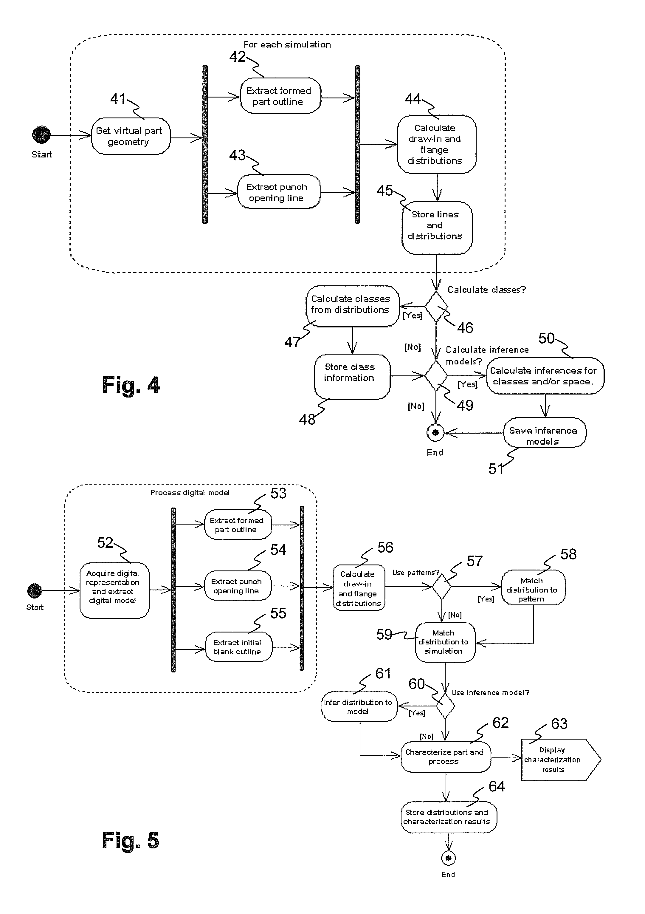
[0043]In a preferred embodiment of the invention, a method is used to calculate material flow (for example draw-in and flange distributions) for a set of simulations, identify patterns within the distributions, calculate mappings between draw-in or flange distributions and process parameters and state variables. Further steps are to acquire a digital model of an actual formed part, extract required information to calculate the material flow distribution for the actual part and infer the actual distribution to the virtual distributions. These steps are preferentially implemented by a computer program which is executed on a data processing system. The computer program may have two parts, one for preparing data and one that works online. This separation is not mandatory, but improves the online efficiency. From the inference it is possible to extract the characterisation of the part in terms of state variables and process parameters. This characterisation is, in a further step, used to...


PUM


Abstract

A method for the characterization of a sheet metal forming product uses the correlation of material flow data to a priori calculated or measured data. It determines whether the product falls within the acceptable production limits in terms of quality, areas of potential defects and an approximation of the process parameters prevailing during its production. The characterization is performed in real-time during production, tool deployment or try-out. The method includes the steps of:providing physical dimensions of an actual sheet metal part; a feature extractor computing, from these physical dimensions, a measured material flow metric representative of the geometry of the part after the forming operation; and a matching unit determining, from reference data and the measured material flow metric, a matching forming operation data set whose associated simulated material flow metric most closely matches the measured material flow metric.

Description

FIELD OF THE INVENTION[0001]The invention relates to the field of forming processes, in particular to the forming of sheet metal. It relates to a method capable of characterizing a sheet metal part in terms of process parameters and state variables, as well as a method for generating reference data from a set of computer simulations for characterizing a sheet metal part, as described in the preamble of the corresponding independent claims. The said method can be used in tool tryout support and quality control.BACKGROUND OF THE INVENTION[0002]Historically, in sheet metal forming processes a set of shaped tools, such as a die and a punch, are used to deform sheets of metal to three-dimensional metal parts. This is accomplished by stamping the desired geometry and inducing sufficient in-plane strain for final product strength and stability. FIG. 1 schematically shows, in the left half, a top view of a sheet metal blank 1 placed between forming tools, schematically represented by a punc...

Claims


Application Information

Patent Timeline
Patent Type & Authority Patents(United States)
IPC IPC(8): G06F7/66G05B19/404G05B19/418
CPCG05B19/404G05B2219/36284G05B2219/37576G05B2219/45137G05B19/41885G05B19/41875
Inventor ZWICKL, TITUSSERVIS, DIMITRIS
Owner NETABTAL MASCHEN
Why Eureka
Eureka Blog
Learn More