Suspension control system

a suspension and control system technology, applied in the direction of resilient suspensions, underwater equipment, position/direction control, etc., can solve the problems of not providing optimal vehicle control and vehicle passenger ride comfort, and achieve the effect of reducing the initial shock, reducing the subsequent oscillation, and increasing the damage for

Active Publication Date: 2016-09-06
PROTEAN ELECTRIC LIMITED
View PDF8 Cites 9 Cited by
  • Summary
  • Abstract
  • Description
  • Claims
  • Application Information

AI Technical Summary

Benefits of technology

[0016]This provides the advantage of allowing the longitudinal compliance damping characteristics to be actively modified, where a longitudinal damping force applied to a wheel of a vehicle can be varied by modifying the torque applied to the wheel from an electric motor based on the relative movement of the wheel. For example, a weak damping force can initially be applied upon a longitudinal jerk first occurring with the damping force gradually being increased by modifying the torque applied to the wheel to apply further dampening to the subsequent oscillations. Accordingly, the present invention allows for the combination of the suppression of oscillations of the strong damping with the initial impact softness of the weakly damped case.
[0017]As such, a vehicle can be provided with a softly damped longitudinal passive suspension system, which is used to minimise the initial shock felt by passengers of the vehicle resulting from a road surface disturbance, with an electric motor being used to modulate the torque applied to a wheel of the vehicle to strengthen the longitudinal damping after the initial shock to minimise the subsequent oscillations.

Problems solved by technology

As such, a suspension system having a longitudinal compliance that is defined by either a strong or weak damper system fails to provide optimum vehicle control and vehicle passenger ride comfort.

Method used


Image

  • Suspension control system
  • Suspension control system
  • Suspension control system

Examples


Embodiment Construction

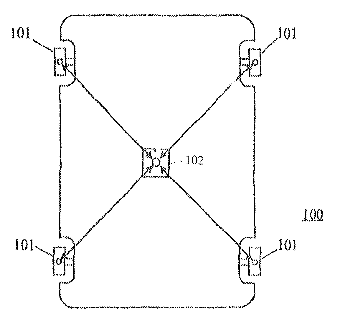
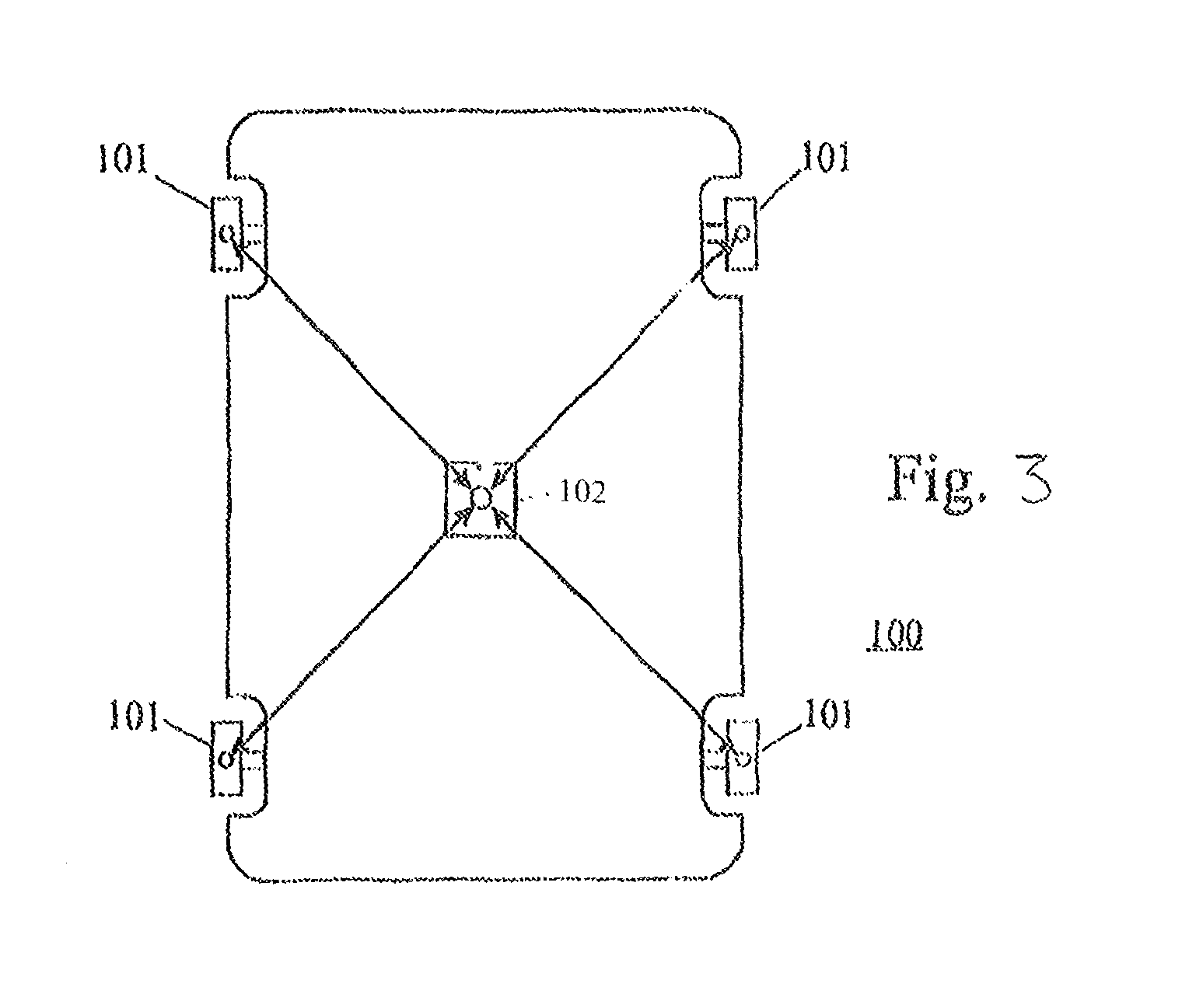
[0028]FIG. 3 illustrates a vehicle 100, for example a car or lorry, having four wheels 101, where two wheels are located in the vehicles forward position in a near side and off side position respectively. Similarly, two additional wheels are located in the vehicles aft position in near side and off side positions respectively, as is typical for a conventional car configuration. However, as would be appreciated by a person skilled in the art, the vehicle may have any number of wheels.

[0029]Incorporated within each wheel 101 is an in-wheel electric motor, as described in detail below. Although the current embodiment describes a vehicle having an in-wheel electric motor associated with each wheel 101, as would be appreciated by a person skilled in the art only a subset of the wheels 101 may have an associated in-wheel electric motor. For example, for a four wheeled vehicle only the front two wheels may have associated in-wheel motors or alternately only the rear two wheels may have ass...


PUM


Abstract

A suspension control system for a vehicle having a wheel (52) mounted to the vehicle via a suspension device mounted to a mounting point on the vehicle with an electric motor being arranged to apply to the wheel a torque for driving the wheel, the suspension control system comprising a controller arranged to modulate a torque applied to the wheel by the electric motor based on the relative longitudinal movement of the wheel with respect to the mounting point on the vehicle.

Description

FIELD OF THE DISCLOSURE[0001]The present invention relates to a suspension control system, in particular a suspension control system for a vehicle having a wheel driven by an electric motor.BACKGROUND[0002]The suspension system of a vehicle has two principle functions, first to isolate the vehicle body and consequently the vehicle's passengers from road inputs, and second to improve the vehicle's road holding by reducing the load variation between the wheels of the vehicle and the ground.[0003]The behaviour of a vehicle's suspension system can be characterised in terms of the suspension system's vertical and longitudinal compliance.[0004]The vertical compliance of vehicle suspension systems is typically created by spring-damper systems that are tuned to provide a good compromise between passenger comfort and handling performance. The springs are chosen to have a resonant frequency of the sprung mass between about 0.7 Hz and 2 Hz. Lower resonant frequencies induce travel sickness whe...

Claims


Application Information

Patent Timeline
Patent Type & Authority Patents(United States)
IPC IPC(8): B60L9/00B60G17/015B60L11/00B60L15/20G06F17/00G06F7/00G05D3/00G05D1/00B60G17/08B60K7/00B63H25/04G06F19/00B60K1/00B63G8/20B62D12/00B62D11/00B62D6/00
CPCB60G17/0157B60G17/08B60L15/20B60G2204/30B60G2300/50B60G2500/10B60K1/00B60K7/0007B60L2220/44B60L2260/28Y02T10/7258Y02T10/72B60G17/015B60K17/043B60W30/02
Inventor HILTON, CHRISTOPHER DAVID
Owner PROTEAN ELECTRIC LIMITED
Why Eureka
Try Eureka