Medical monitoring hub

a medical monitoring and hub technology, applied in the field of patient monitoring devices, can solve problems such as chaos, device disarray, and potentially chaotic experience, and achieve the effects of reducing patient pain, reducing patient discomfort, and reducing patient comfor

Active Publication Date: 2016-09-06
JPMORGAN CHASE BANK NA +1
View PDF986 Cites 429 Cited by
  • Summary
  • Abstract
  • Description
  • Claims
  • Application Information

AI Technical Summary

Benefits of technology

[0009]Therefore, the present disclosure relates to a patient monitoring hub that is the center of patient monitoring and treatment activities for a given patient. Embodiments of the patient monitoring hub interface with legacy devices without necessitating legacy reprogramming, provide flexibility for interfacing with future devices without necessitating software upgrades, and offer optional patient electrical isolation. In an embodiment, the hub includes a large display dynamically providing information to a caregiver about a wide variety of measurement or otherwise determined parameters. Additionally, in an embodiment, the hub includes a docking station for a portable patient monitor. The portable patient monitor may communicate with the hub through the docking station or through various wireless paradigms known to an artisan from the disclosure herein, including WiFi, Bluetooth, Zigbee, or the like.
[0010]In still other embodiments, the portable patient monitor modifies its screen when docked. The undocked display indicia is in part or in whole transferred to a large dynamic display of the hub and the docked display presents one or more anatomical graphics of monitored body parts. For example, the display may present a heart, lungs, a brain, kidneys, intestines, a stomach, other organs, digits, gastrointestinal systems or other body parts when it is docked. In an embodiment, the anatomical graphics may advantageously be animated. In an embodiment, the animation may generally follow the behavior of measured parameters, such as, for example, the lungs may inflate in approximate correlation to the measured respiration rate and / or the determined inspiration portion of a respiration cycle, and likewise deflate according to the expiration portion of the same. The heart may beat according to the pulse rate, may beat generally along understood actual heart contraction patterns, and the like. Moreover, in an embodiment, when the measured parameters indicate a need to alert a caregiver, a changing severity in color may be associated with one or more displayed graphics, such as the heart, lungs, brain, or the like. In still other embodiments, the body portions may include animations on where, when or how to attach measurement devices to measurement sites on the patient. For example, the monitor may provide animated directions for CCHD screening procedures or glucose strip reading protocols, the application of a forehead sensor, a finger or toe sensor, one or more electrodes, an acoustic sensor, and ear sensor, a cannula sensor or the like.

Problems solved by technology

Sometimes, the disparity in devices leads to a need to simply print and store paper from each device in a patient's file for caregiver review.
The result of such device disparity is often a caregiver environment scattered with multiple displays and alarms leading to a potentially chaotic experience.
Such chaos can be detrimental to the patient in many situations including surgical environments where caregiver distraction is unwanted, and including recovery or monitoring environments where patient distraction or disturbance may be unwanted.
However, as medical device technology expands, such multi-monitor devices begin to be obsolete the moment they are installed.

Method used


Image

  • Medical monitoring hub
  • Medical monitoring hub
  • Medical monitoring hub

Examples


Embodiment Construction

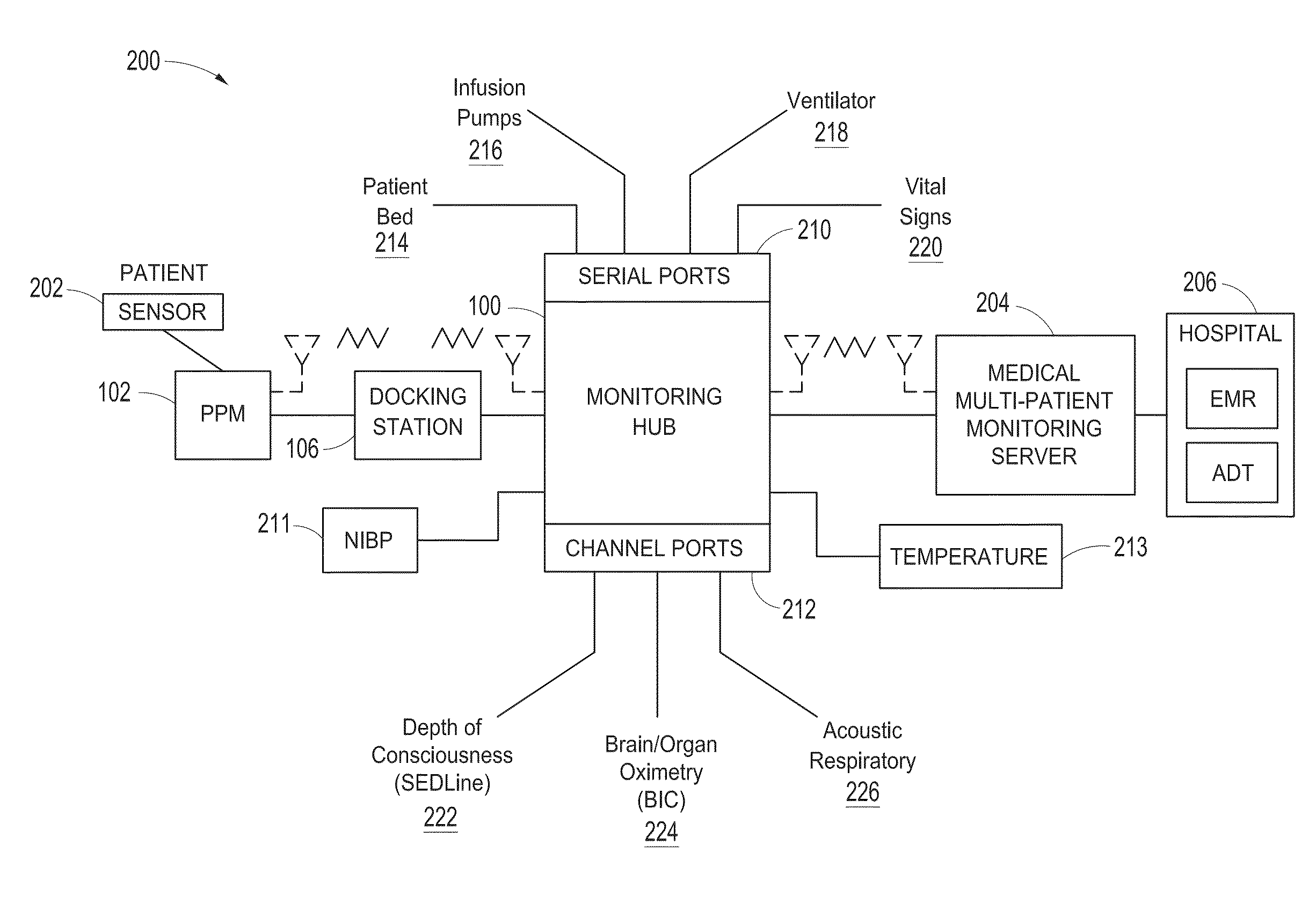
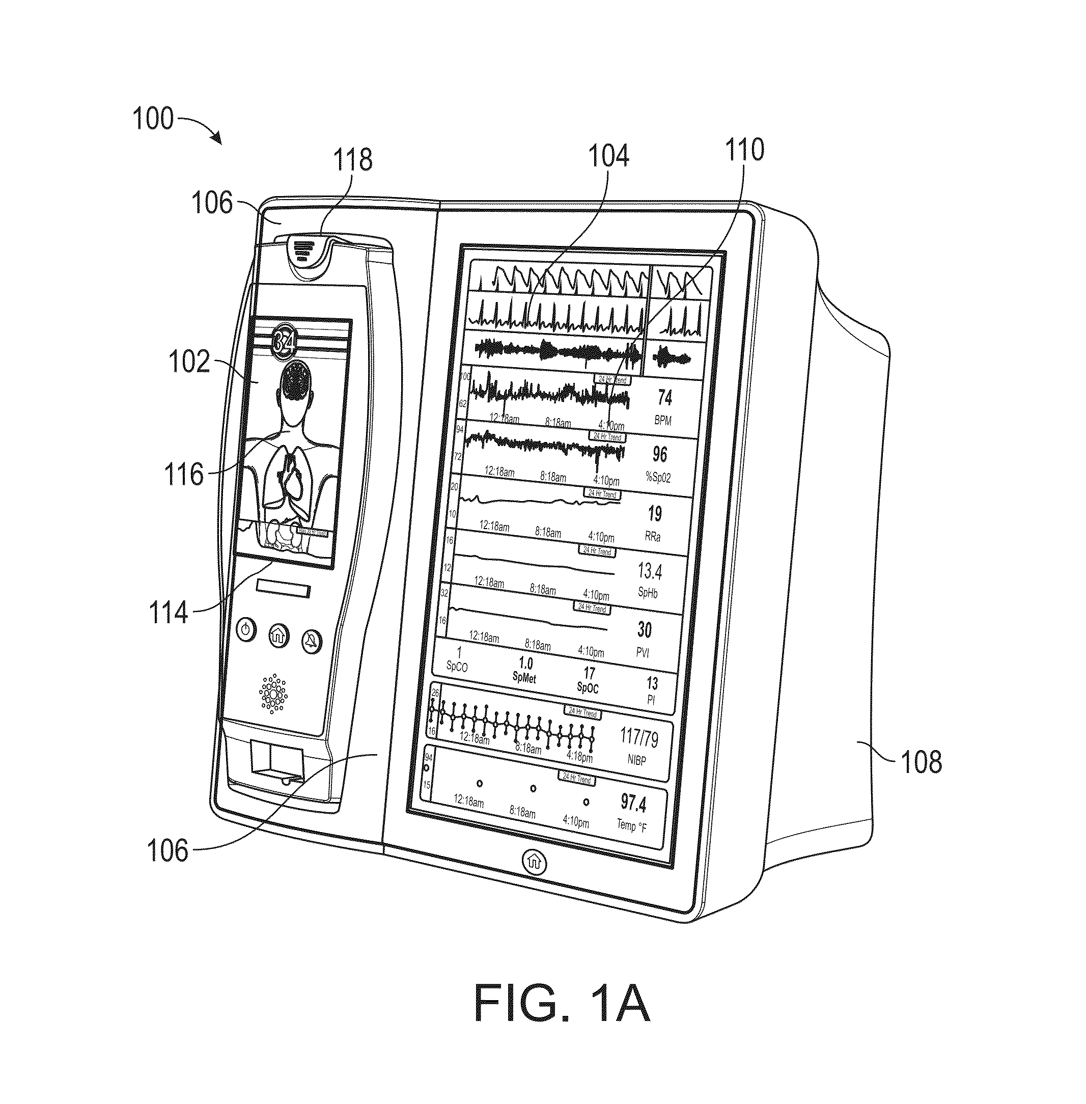
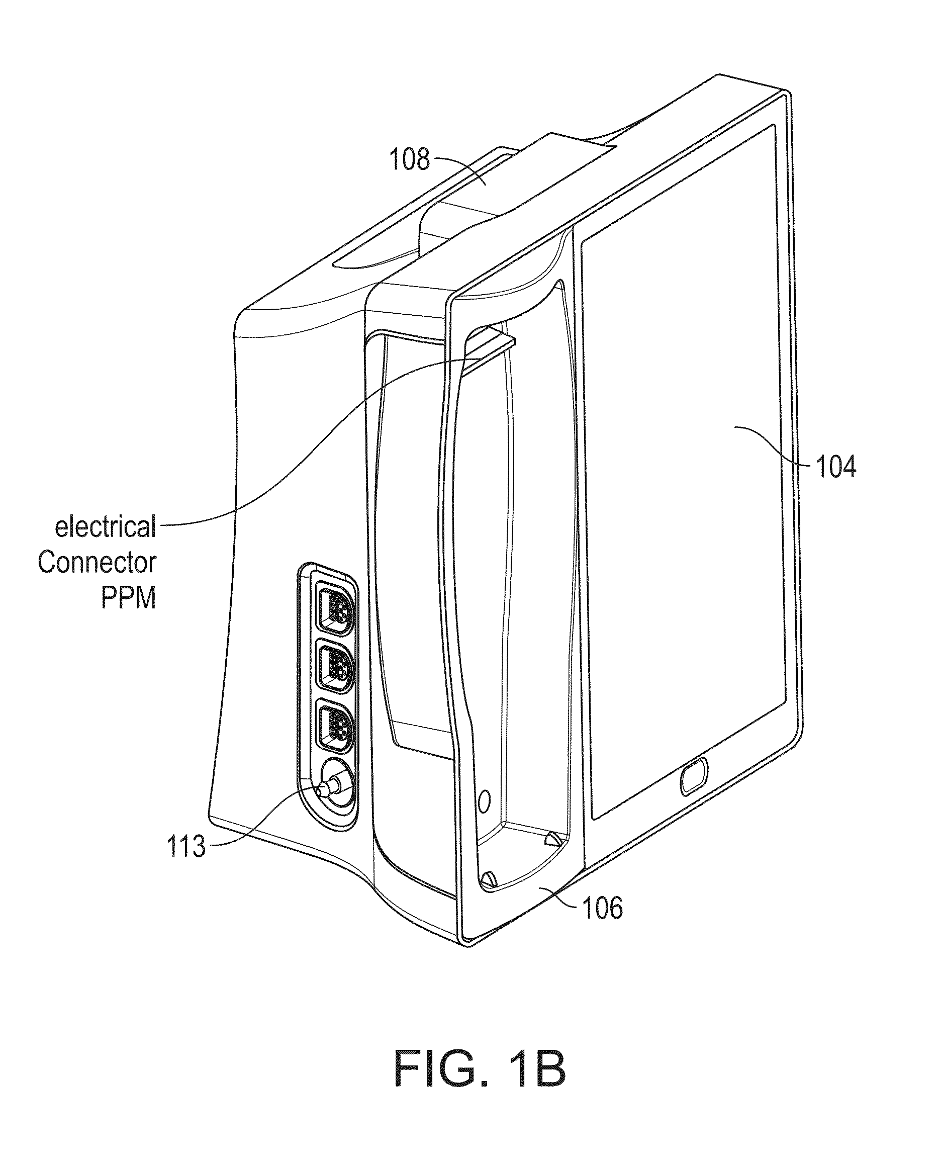
[0037]The present disclosure relates to a medical monitoring hub configured to be the center of monitoring activity for a given patient. In an embodiment, the hub comprises a large easily readable display, such as an about ten (10) inch display dominating the majority of real estate on a front face of the hub. The display could be much larger or much smaller depending upon design constraints. However, for portability and current design goals, the preferred display is roughly sized proportional to the vertical footprint of one of the dockable portable patient monitors. Other considerations are recognizable from the disclosure herein by those in the art.

[0038]The display provides measurement data for a wide variety of monitored parameters for the patient under observation in numerical or graphic form, and in various embodiments, is automatically configured based on the type of data and information being received at the hub. In an embodiment, the hub is moveable, portable, and mountabl...


PUM


Abstract

The present disclosure includes a medical monitoring hub as the center of monitoring for a monitored patient. The hub includes configurable medical ports and serial ports for communicating with other medical devices in the patient's proximity. Moreover, the hub communicates with a portable patient monitor. The monitor, when docked with the hub provides display graphics different from when undocked, the display graphics including anatomical information. The hub assembles the often vast amount of electronic medical data, associates it with the monitored patient, and in some embodiments, communicates the data to the patient's medical records.

Description

PRIORITY CLAIM AND RELATED APPLICATIONS[0001]This application claims a priority benefit under 35 U.S.C. §119 to the following U.S. Provisional Patent Applications:[0002]Serial No.DateTitle61 / 547,017,Oct. 13, 2011,Visual Correlation of PhysiologicalInformation,61 / 547,577,Oct. 14, 2011,Visual Correlation of PhysiologicalInformation,61 / 597,120,Feb. 9, 2012,Visual Correlation of PhysiologicalInformation, and.61 / 703,773Sep. 20, 2012Medical Monitoring Hub[0003]Each of the foregoing disclosures is incorporated by reference herein in its entirety.FIELD OF THE DISCLOSURE[0004]The present disclosure relates generally to patient monitoring devices and specifically to a patient monitor and medical data communication hub.BACKGROUND OF THE DISCLOSURE[0005]Today's patient monitoring environments are crowded with sophisticated and often electronic medical devices servicing a wide variety of monitoring and treatment endeavors for a given patient. Generally, many if not all of the devices are from di...

Claims


Application Information

Patent Timeline
Patent Type & Authority Patents(United States)
IPC IPC(8): G06F13/40G06F19/00A61B5/00A61M16/00A61B5/021A61B5/08A61B5/1455A61M5/172A61B5/0205
CPCG06F13/4081A61B5/0002A61B5/002A61M16/0051G06F19/3406A61B5/021A61B5/02055A61B5/0816A61B5/14551A61B5/4821A61B5/4836A61B2560/0214A61B2562/08A61B2562/227A61M5/172A61M2205/18A61M2205/3368A61M2205/3375A61M2205/3561A61M2205/3569A61M2205/3584A61M2205/3592A61M2205/505A61M2209/086A61M2230/04A61M2230/10A61M2230/201A61M2230/205A61M2230/208A61M2230/30A61M2230/42A61M2230/50A61M16/021G16H40/63G16H10/60A61B5/318A61B5/369A61B5/316A61B5/01A61B5/02416A61B5/14539A61B5/4866A61B5/4875A61B5/7425A61B5/743A61B5/746A61B7/003A61B2560/0475A61B2562/222A61B5/0022A61B5/742G06F1/1632A61B2560/0209
Inventor AL-ALI, AMMARKINAST, ERIC KARLMUHSIN, BILALTRIMAN, BENJAMIN
Owner JPMORGAN CHASE BANK NA
Why Eureka
Try Eureka