Electrical plug-in connector

a plug-in connector and plug-in technology, applied in the direction of electrical equipment, contact members penetrating/cutting insulation/cable strands, coupling device connections, etc., can solve the problems of bearing pins, bearing pins, and the protruding locking protrusions that serve for locking, and achieve the effect of precise locking, precise guiding and stable connection

Active Publication Date: 2016-09-06
ERNI PRODION GMBH
View PDF63 Cites 6 Cited by
  • Summary
  • Abstract
  • Description
  • Claims
  • Application Information

AI Technical Summary

Benefits of technology

[0007]The electrical plug-in connector according to the invention, in contrast, has the advantage that the locking clip does not have to be fastened to a housing, but rather can be handled as a separate component. This is therefore advantageous because, for example, if the locking clip is damaged, an exchange of the locking clip with an undamaged locking clip is easily possible. Furthermore, the locking clip according to the invention is designed to be substantially more massive and stable than the locking clips known from the prior art. It is particularly advantageous that the locking clip according to the invention is, in particular, able to be a secondary locking clip which provides additional security for a plug-in connection that is already locked, such that this is able to be used in particularly critical environments (for example environments that are subject to heavy vibrations and so forth). A tongue having a latching hook, arranged on the second housing part, for example, and an opening arranged in the first housing part, with which opening the latching hook engages, are provided as the primary locking agent. A locking clip is provided according to the invention which is able to be locked in / on the second or first housing part while it encloses the first or second housing part substantially parallel to the plugging direction, when both housing parts are plugged into each other. A particularly stable connection of the two plug-in connector parts that are plugged into each other is hereby implemented.
[0008]By the measures described herein, advantageous developments and improvements of the plug-in connector are possible.
[0012]Provision is highly advantageously made for the U-shaped legs to have grooves as guide elements on their respective inner side facing the first or second housing part, with which grooves protrusions that are adapted to them and are arranged on the outer sides running parallel to the plugging direction engage in a sliding manner. The guide elements are therefore implemented by grooves and by protrusions engaging therewith. This enables, on the one hand, a precise guiding of the locking clip, but on the other hand enables an optimal fastening of the locking clip to the housing part having the protrusions.
[0010]Moreover, provision is advantageously made for latch elements for locking with the counterpart latch elements arranged on the clip arms to be provided in the second or first housing part. The counterpart latch elements arranged on the clip arms lock with the latch elements, wherein a precise guiding, and therefore also a precise locking of the latch elements to one another is ensured by the guide elements.
[0011]Purely as a matter of principle, the locking clips may be designed in a different manner. One particularly advantageous embodiment provides that the locking clips are designed in a U shape with two U-shaped legs that are bent fundamentally orthogonally from a base. Such a U-shaped design is used particularly advantageously in the case of mostly cuboidal plug-in connector housing parts.
[0012]Provision is highly advantageously made for the U-shaped legs to have grooves as guide elements on their respective inner side facing the first or second housing part, with which grooves protrusions that are adapted to them and are arranged on the outer sides running parallel to the plugging direction engage in a sliding manner. The guide elements are therefore implemented by grooves and by protrusions engaging therewith. This enables, on the one hand, a precise guiding of the locking clip, but on the other hand enables an optimal fastening of the locking clip to the housing part having the protrusions.
[0013]Provision is particularly advantageously made for the U-shaped legs to have latching hooks as counterpart elements on their ends, said latching hooks interacting with snap-in noses arranged on the first or second housing part. The interaction of the grooves, together with the protrusions and the latching hooks, with the snap-in noses arranged on the housing part enables precise guiding of the U-shaped legs and thus also a precise latching of the latching hooks into the snap-in noses. In order to simplify this latching, provision is advantageously made for the latching hooks and the snap-in noses to have sliding surfaces on their sides facing one another that are adapted to one another and that run obliquely.
[0014]The locking clips can, purely as a matter of principle, consist of highly different materials. They are particularly advantageously designed as a plastic part which is not only easy to produce, but is also particularly light and at the same time has insulating properties.

Problems solved by technology

This rotatable mounting of both locking clips requires complex, time-consuming production; moreover, the bearing pins and, in particular, the locking protrusions that serve for the locking are easily exposed to damage.

Method used


Image

  • Electrical plug-in connector
  • Electrical plug-in connector
  • Electrical plug-in connector

Examples


Embodiment Construction

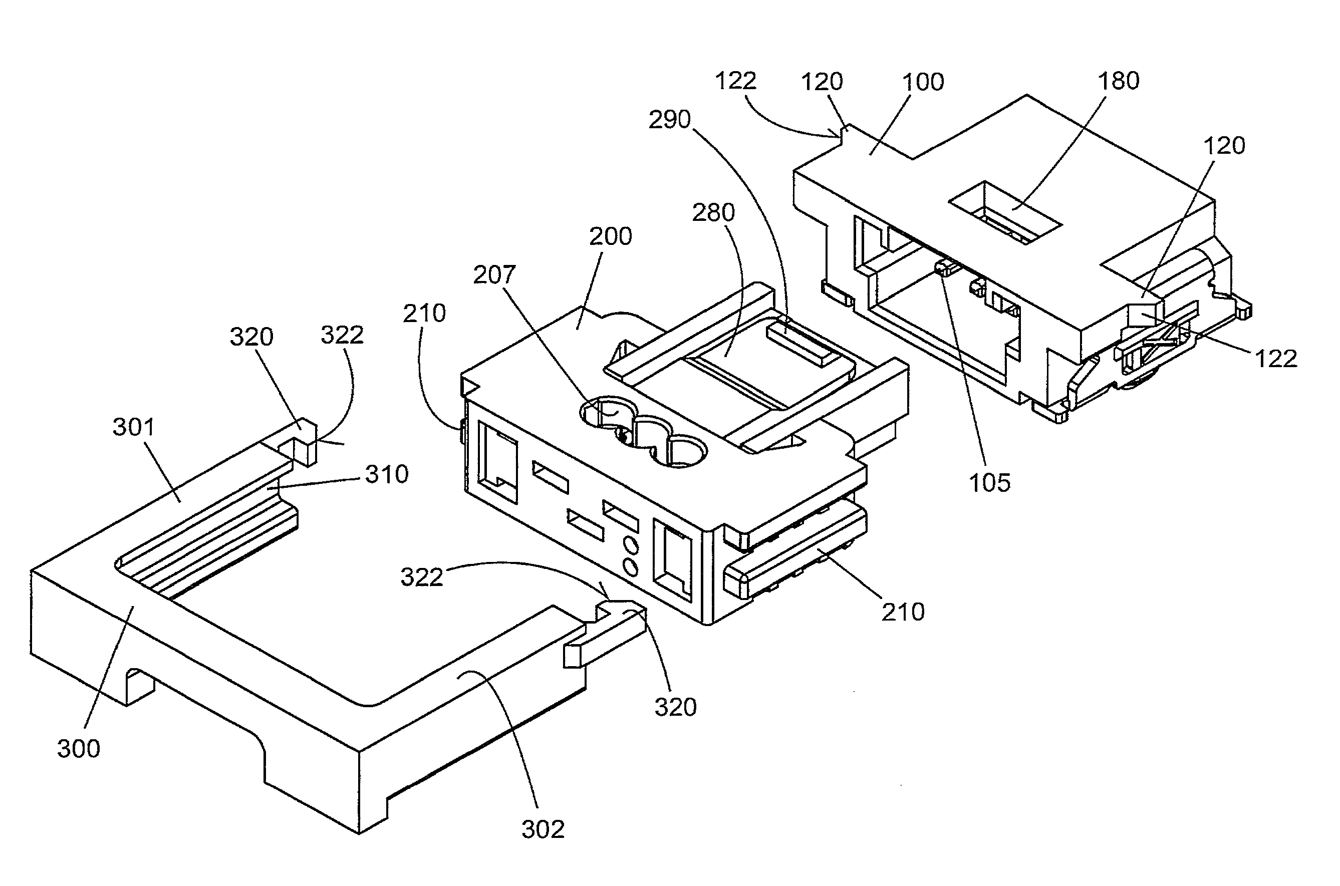
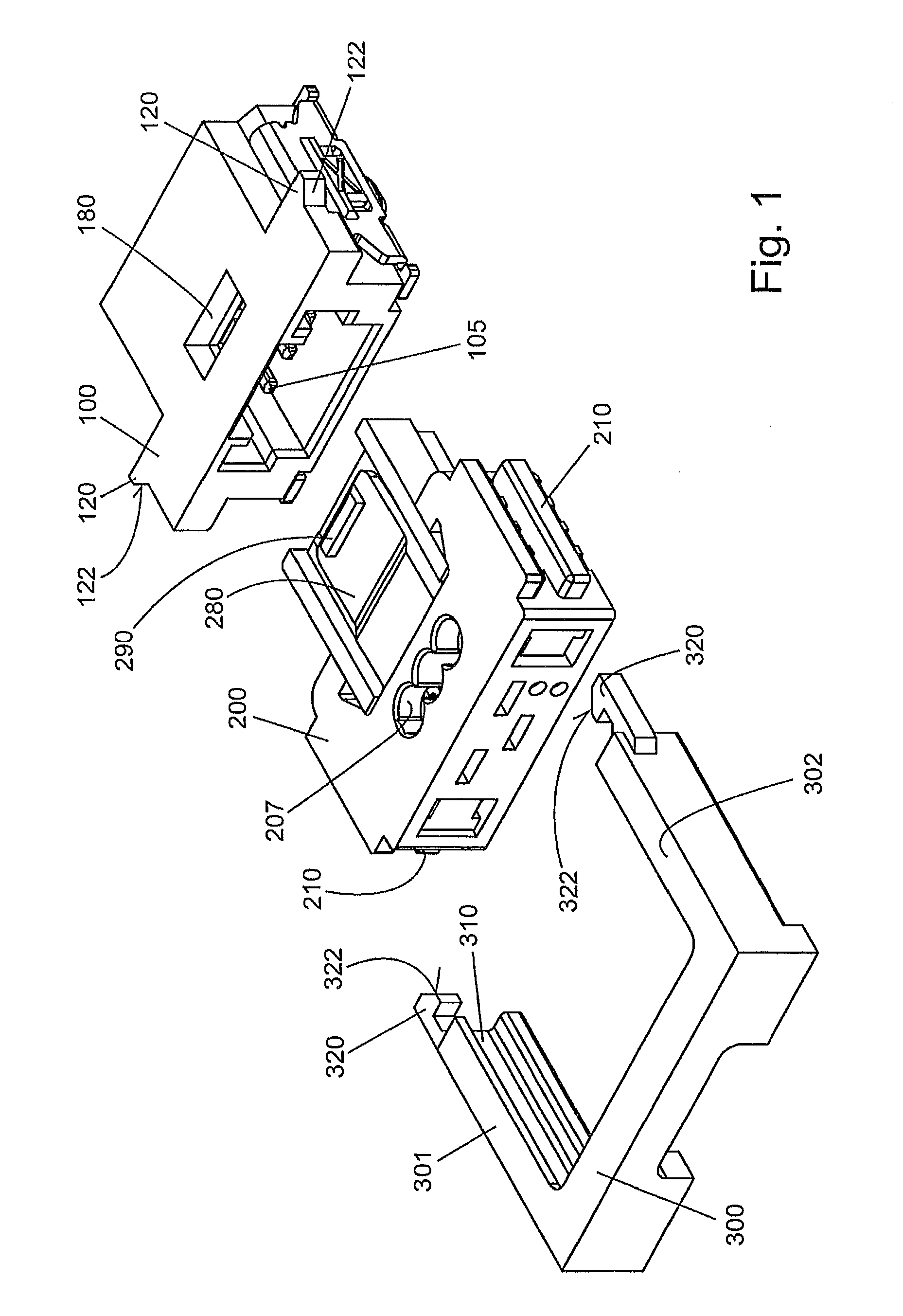
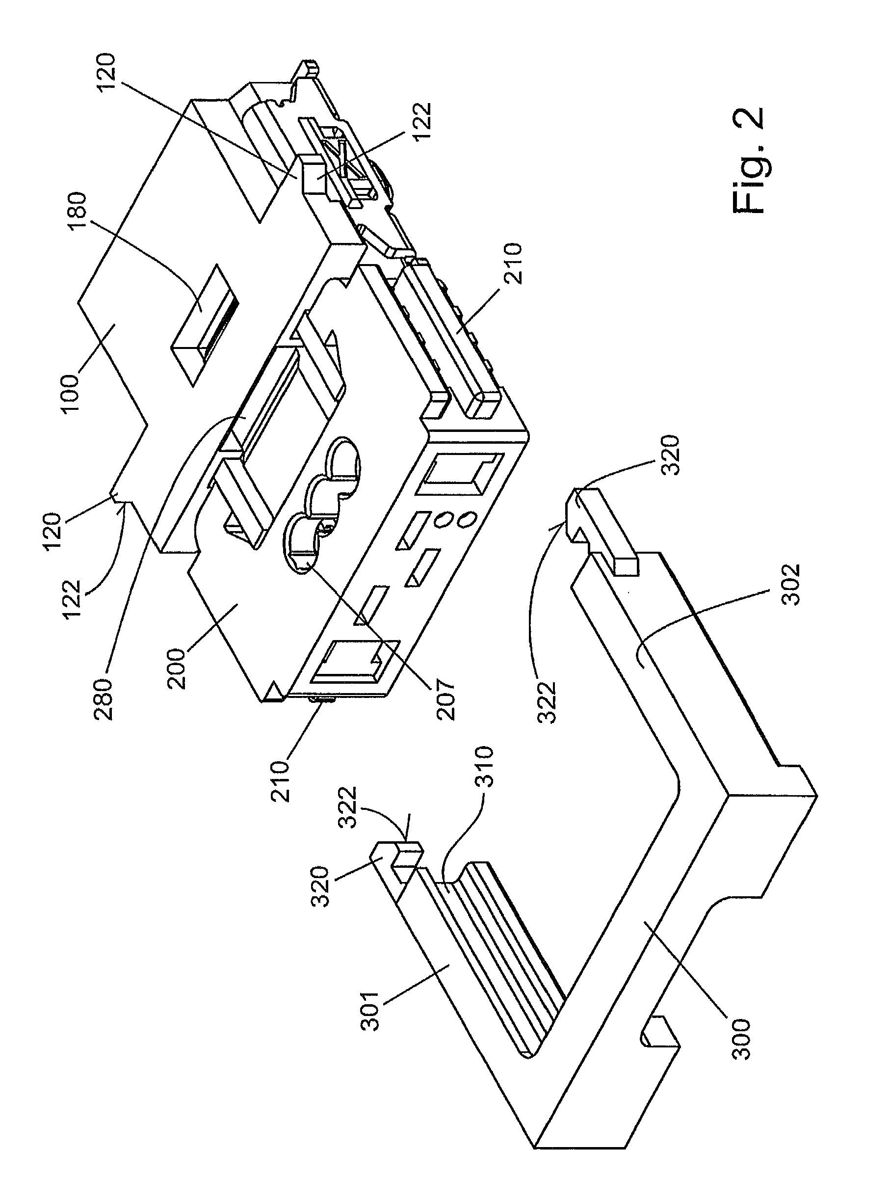
[0020]An electrical plug-in connector, depicted in FIGS. 1 to 3 in different plugging states, has a first housing part 100 in which first plug contact elements, for example blade contact elements 105, are arranged. Adapted to this first housing part 100 is a second housing part 200, which is able to be plugged into the first housing part 100 in a manner that is known in itself, and in which corresponding counterpart contact elements, i.e. spring contacts (not visible here) are arranged.

[0021]A locking clip 300 is moreover provided, which has a substantially U-shaped configuration with U-shaped legs. 301, 302. The inner side of the U-shaped legs 301, 302 has U-shaped grooves 310 which are adapted to corresponding protrusions 210 that are designed here to be cuboidal, said protrusions being fitted onto the outer sides of the second housing part 200 of the plug-in connector, in such a way that the cuboidal protrusions 210 are able to be slid into the grooves 310 of the locking clip 300...


PUM


Abstract

An electrical plug-in connector having a first housing part and having a second housing part, blade contact elements being arranged in the first or second housing part and spring contact elements being arranged in the second or first housing part which are adapted to the blade contacts and can be inserted therein, has a locking clip which, when it engages around the first or second housing part in a manner substantially parallel to the plug-in direction when the two housing parts are plugged into each other, can be locked in or on the second or first housing part.

Description

CROSS REFERENCE TO RELATED APPLICATIONS[0001]This application is the National Stage of PCT / DE2013 / 000812 filed on Dec. 17, 2013, which claims priority under 35 U.S.C. §119 of German Application No. 10 2012 025 106.8 filed on Dec. 21, 2012, the disclosure of which is incorporated by reference. The international application under PCT article 21(2) was not published in English.[0002]The invention relates to an electrical plug-in connector having a first housing part and a second housing part, wherein blade contact elements are arranged in the first or second housing part and spring contact elements which are adapted to the blade contact elements and are able to be inserted into them are arranged in the second or first housing part.PRIOR ART[0003]Such plug-in connectors are widespread in the prior art.[0004]Thus, for example, an electrical plug-in connector of the type conforming to its genre arises from DE 10 2004 054 203 A1, in which an insulation displacement plug-in contact strip is...

Claims


Application Information

Patent Timeline
Patent Type & Authority Patents(United States)
IPC IPC(8): H01R13/508H01R13/639H01R13/627H01R4/24
CPCH01R13/508H01R13/6272H01R13/639H01R4/2433
Inventor LAPPOEHN, JUERGEN
Owner ERNI PRODION GMBH
Why Eureka
Try Eureka