Nasal irrigator

Active Publication Date: 2016-09-13
MONAGHAN MEDICAL
View PDF50 Cites 5 Cited by
  • Summary
  • Abstract
  • Description
  • Claims
  • Application Information

AI Technical Summary

Benefits of technology

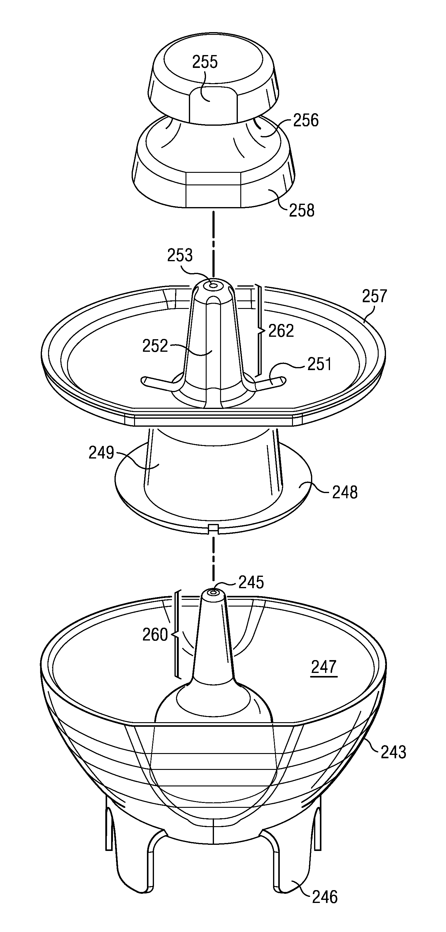
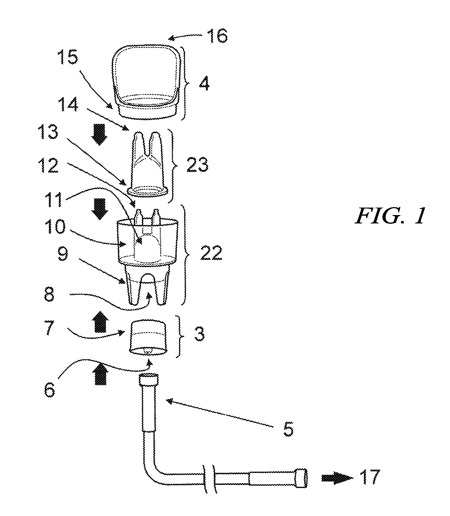
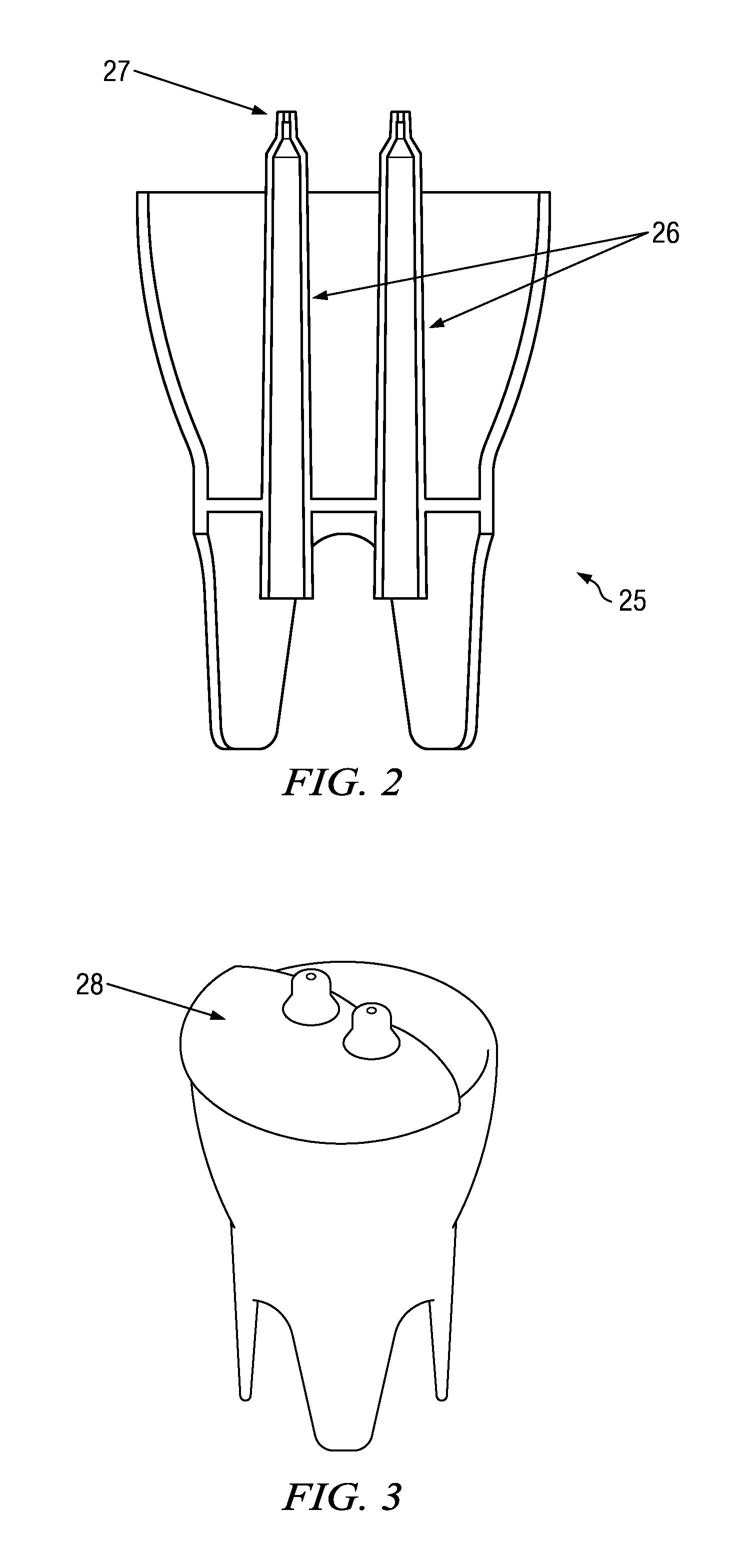
[0006]A nasal nebulizer device comprises a main canister comprising at least one air outlet or exit port and a rim surrounding a reservoir for holding fluid; and an insert with a base that fits within the canister, wherein the insert comprises a tube portion ending in a common bell housing above the base, wherein the base comprises a groove along its bottom face forming a communication channel between the canister and the common bell housing, and wherein the fluid channel is larger in diameter than the air exit port, thereby providing a small space between the outer surface of the air exit port and the inner surface of the fluid channel that allows fluid from the reservoir to be drawn through the communication channel and between the air exit port and the fluid channel such that the fluid is expelled as a mist in an aerosol plume through an exit hole in the fluid channel due to a venturi effect created by pressurized air flow from the air exit port. Thus, when pressurized air is inserted through an inlet at the bottom of the canister, a venturi effect is created, and the fluid is drawn from the reservoir and through the fluid channel to be expelled near the air exit port as a mist through an exit hole in the fluid channel. The fluid of the canister is atomized and injected directly into the nasal cavity. In some embodiments, the insert may mate with the canister such that the two are rigidly but not necessarily inseparably coupled together.
[0007]In a first aspect, the insert and canister of a nasal nebulizer are affixed or attached to one another to form a single integral structure or piece, thereby providing for a single usage nasal nebulizer. In one embodiment, the insert is bonded to the canister along the bottom face of the base of the insert. In another embodiment, the insert is bonded to the canister around a periphery of the base. In another embodiment, the connection may comprise a temporary or mechanical mating between the insert and the canister. A cap without holes or protrusions extending therethrough can be used to cover or plug the exit hole of the fluid channel and the air exit port in one embodiment, thereby sealing fluid within the reservoir until the cap is removed. The cap prevents leakage of the fluid from the reservoir and also allows for long-term storage and delivery of a pre-filled nasal nebulizer that is ready to use.

Problems solved by technology

However, some cases require the introduction of liquid droplets to the patient's nasal passages.

Method used


Image

  • Nasal irrigator
  • Nasal irrigator
  • Nasal irrigator

Examples


Embodiment Construction

[0033]The present invention improves upon current nebulizer designs and provides a method of delivering fluid to the nasal passages with little interaction required by the user, under sufficient pressure to stent-open the airway, and with particles of a size to ensure that the majority of the mist is retained or deposited within the upper airway. The invention also provides a nasal nebulizer designed to deliver a mist to the upper airway through both nostrils simultaneously.

[0034]In one aspect, a nasal nebulizer of the present invention comprises a main canister with a reservoir for holding fluid, wherein the canister includes at least two air exit ports; a removable insert with a circular base that fits within said main canister, wherein the insert includes at least two fluid channels that mate with said air exit ports of the main canister, said fluid channels comprising two tubes ending in a common bell housing above the base, wherein said base holds the insert just off of the mai...


PUM

PropertyMeasurementUnit
particle sizeaaaaaaaaaa
angleaaaaaaaaaa
specific angleaaaaaaaaaa

Abstract

A nasal nebulizer contains a main canister with at least one air exit port and an insert with at least one fluid channel. The fluid channel ends in a common bell housing above a base of the insert, which rests within the canister. The insert and the canister may form one integral unit for single usage, where a cap plugs the air exit port and the fluid channel, allowing for the transport or long-term storage of fluids within the nebulizer device. The insert may include an extension extending out to the canister and a vertical groove may extend down the fluid channel to a hole in the extension, which upon use helps create a vacuum that pulls in deflected fluid for re-use. The nebulizer may also contain a filter surrounding the tube portion near the top of the canister to catch any extraneous matter expelled from the nose during usage.

Description

CROSS-REFERENCE TO RELATED APPLICATIONS[0001]This application is a continuation-in-part of and claims filing priority rights with respect to currently U.S. patent application Ser. No. 12 / 633,269 filed Dec. 8, 2009, which published on Jun. 9, 2011, as U.S. Publication No. 2011 / 0137290; Ser. No. 12 / 787,576 filed May 26, 2010, which published on Jun. 9, 2011, as U.S. Publication No. 2011 / 0132354; and Ser. No. 12 / 829,198 filed Jul. 1, 2010. U.S. patent application Ser. No. 12 / 787,576 is, in turn, a continuation-in-part and claims filing priority rights with respect to U.S. patent application Ser. No. 12 / 633,269. The technical disclosures of all of the above-mentioned applications are hereby incorporated herein by reference.TECHNICAL FIELD[0002]The present invention generally relates to devices used for administering fluid to the upper airway in mist or droplet form, either for the irrigation of the nasal passages or the delivery of medication in a nasal nebulizer.BACKGROUND OF THE INVEN...

Claims


Application Information

Patent Timeline
Patent Type & Authority Patents(United States)
IPC IPC(8): A61M3/02A61M11/00A61M11/02A61M15/08A61M11/06
CPCA61M3/025A61M3/0279A61M11/001A61M11/02A61M11/06A61M15/08A61M2210/0618Y10T29/494A61M3/0208A61M3/0216A61M3/022
Inventor FLICKINGER, WILLIAM J.QUACKENBUSH, JOHN
Owner MONAGHAN MEDICAL
Why Eureka
Try Eureka