Modular scope mount assembly

a modular, scope technology, applied in the direction of weapon components, sighting devices, weapons, etc., can solve the problems of affecting the ability of shooters to quickly make precise, affecting the accuracy of the target, and the significant difference between the parabolic travel path. achieve the effect of increasing the usable elevation (or vertical) adjustmen

Active Publication Date: 2016-09-13
ZIMMER TRENT
View PDF2 Cites 12 Cited by
  • Summary
  • Abstract
  • Description
  • Claims
  • Application Information

AI Technical Summary

Benefits of technology

[0006]Implementations of a modular scope mount assembly are provided. In some implementations, the modular scope mount assembly may be used to secure a telescopic sight to a firearm (e.g., a rifle and / or a carbine). In some implementations, the modular scope mount assembly may be used to co-mount a telescopic sight and a reflex sight to a firearm. In some implementations, the modular scope mount assembly may be configured to place a reflex sight on the right side and / or left side of a co-mounted telescopic sight. In some implementations, the modular scope mount assembly may be configured to allow a user to change (increase or decrease) the eye relief between the user and the co-mounted reflex sight(s).

Problems solved by technology

However, these mounting options have several disadvantages.
First, the user may not be able to maintain a cheek weld when using the co-mounted reflex sight.
Second, the distance between the co-mounted reflex sight and the bore of the firearm will cause there to be a significant difference between the parabolic travel path of a bullet fired from the firearm and the aiming point of the reflex sight.
This can negatively affect the shooters ability to rapidly make precise shots at short range using the reflex sight.

Method used


Image

  • Modular scope mount assembly
  • Modular scope mount assembly
  • Modular scope mount assembly

Examples


Embodiment Construction

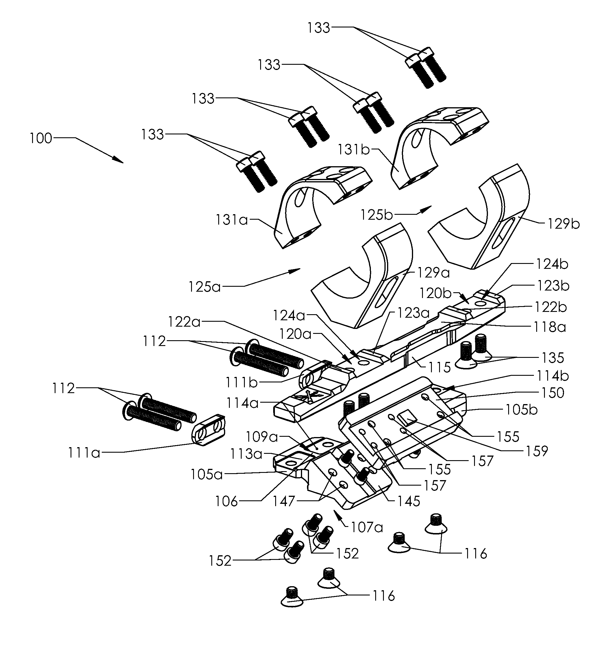
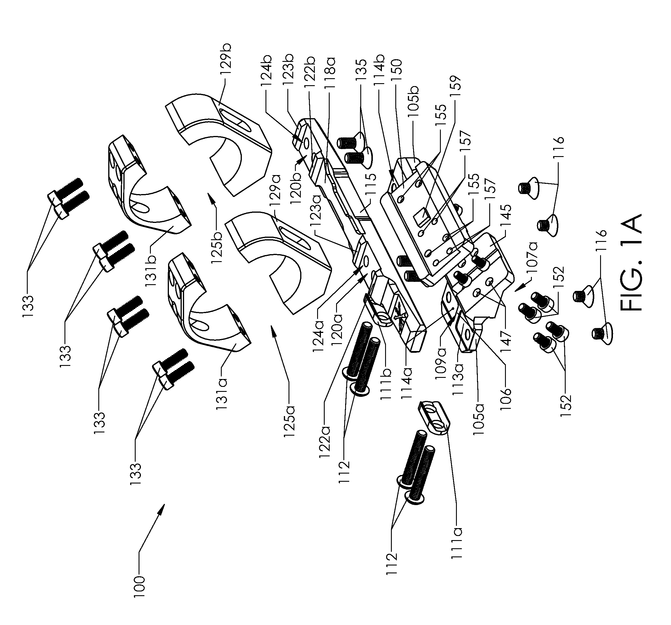
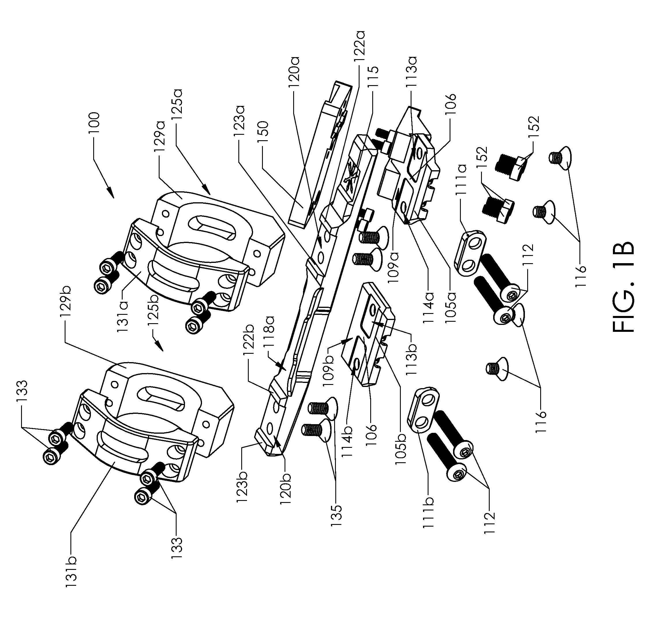
[0014]FIGS. 1A-1B, 2A-2B, 3A-3B, and 4-5 illustrate an example modular scope mount assembly 100 according to the present disclosure. In some implementations, the modular scope mount assembly 100 may be used to secure a telescopic sight 230 to a firearm (e.g., a rifle and / or a carbine). In some implementations, the modular scope mount assembly 100 may be used to co-mount a telescopic sight 230 and a reflex sight 250 to a firearm (see, e.g., FIG. 5).

[0015]As shown in FIGS. 1A-1B, in some implementations, the modular scope mount assembly 100 may comprise a first base 105a, a second base 105b (collectively bases 105), a bridge 115, a first scope ring 125a, and a second scope ring 125b (collectively scope rings 125). In some implementations, the modular scope mount assembly 100 may further comprise an adaptor plate 150 to which a reflex sight 250 can be mounted (see, e.g., FIG. 5). In some implementations, the bridge 115 may be removably secured to the first base 105a and the second base...


PUM


Abstract

Implementations of a modular scope mount assembly are provided. In some implementations, the modular scope mount assembly may be used to secure a telescopic sight to a firearm (e.g., a rifle and / or a carbine). In some implementations, the modular scope mount assembly may be used to co-mount a telescopic sight and a reflex sight to a firearm. In some implementations, the modular scope mount assembly may be configured to place a reflex sight on the right side and / or left side of a co-mounted telescopic sight. In some implementations, the modular scope mount assembly may be configured to allow a user to change (increase or decrease) the eye relief between the user and the co-mounted reflex sight(s).

Description

CROSS REFERENCE TO RELATED APPLICATION[0001]This application claims the benefit of U.S. patent application Ser. No. 62 / 104,323, which was filed on Jan. 16, 2015, and is incorporated herein by reference in its entirety.TECHNICAL FIELD[0002]This disclosure relates to implementations of a modular scope mount assembly.BACKGROUND[0003]Telescopic sights and reflex sights are two sighting systems routinely used to aim a firearm. In general, telescopic sights are used to improve long range accuracy with a firearm while reflex sights are used at short range for rapid acquisition of and transitions between targets. Many shooters (e.g., warfighters or mult gun competitors) find it advantageous to mount both a telescopic sight and a reflex sight on their rifle. A rifle equipped with both telescopic and reflex sights allows the shooter to rapidly transition between a sighting system optimized for long range engagements and a sighting system optimized for short range engagements.[0004]A variety o...

Claims


Application Information

Patent Timeline
Patent Type & Authority Patents(United States)
IPC IPC(8): F41G1/387F41G11/00
CPCF41G11/004F41G11/003F41G11/001
Inventor ZIMMER, TRENT
Owner ZIMMER TRENT
Why Eureka
Try Eureka