Supercharge Your Innovation With Domain-Expert AI Agents!

Device for recovering and converting heat energy into electrical energy

Active Publication Date: 2016-09-13
COMMISSARIAT A LENERGIE ATOMIQUE ET AUX ENERGIES ALTERNATIVES +1
View PDF16 Cites 7 Cited by
  • Summary
  • Abstract
  • Description
  • Claims
  • Application Information

AI Technical Summary

Benefits of technology

Enables efficient conversion of heat energy into electrical energy with miniaturization and flexibility in device orientation, suitable for various heat sources, including portable electronics and industrial applications, by utilizing surface energy gradients and piezoelectric materials to generate cyclic pressure peaks.

Problems solved by technology

This device has the drawback of requiring to orient the second wall below the first wall depending on the gravity forces to ensure fall of condensed drops.

Method used


Image

  • Device for recovering and converting heat energy into electrical energy
  • Device for recovering and converting heat energy into electrical energy
  • Device for recovering and converting heat energy into electrical energy

Examples


Embodiment Construction

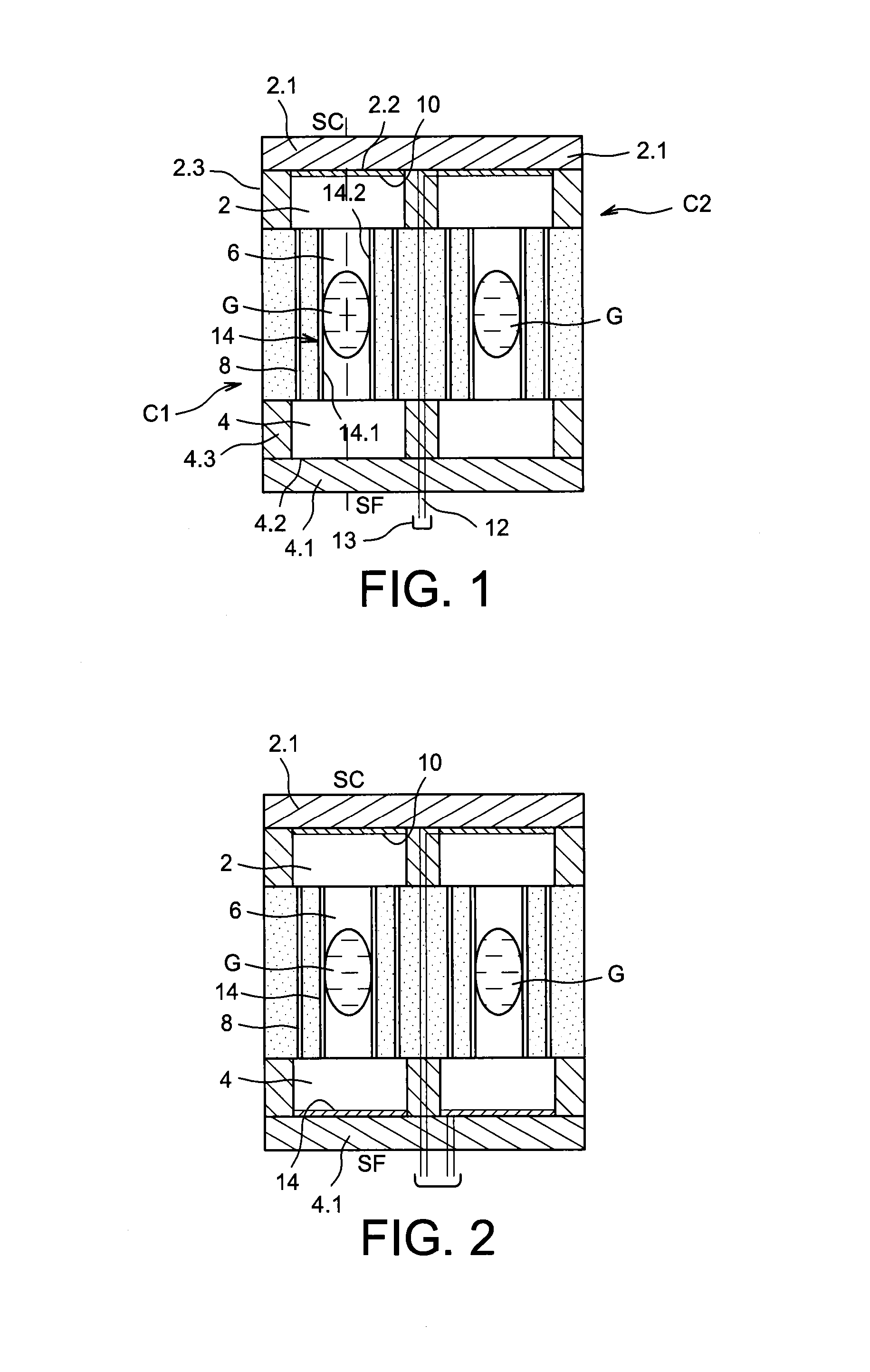
[0046]In FIG. 1, an exemplary embodiment of a recovering and converting device comprising a first cavity 2, a second cavity 4, a channel 6, called a primary channel connecting the first cavity 2 and the second cavity 4, and second channels 8, called secondary channels, connecting the first cavity 2 and the second cavity 4 can be seen. In the example represented, the primary channel extends along a longitudinal axis X. The assembly thus formed will be referred to as cells. The device represented in FIG. 1 comprises two cells C1 and C2.

[0047]The cavity 2 comprises a first and a second end wall 2.1, 2.2 and side walls 2.3. In the example represented, the first end wall 2.1 is for contacting a hot source HS; the wall 2.1 will be referred to as “hot wall” in the following of the description. The temperature reached by the hot wall 2.1 is such that it ensures vaporising of the fluid contained in the device. Therefore, it is at least equal to the boiling temperature of the fluid. Exemplary...


PUM


Abstract

A device for converting heat energy into electrical energy including cells, the cells including: a first cavity with one wall for contacting a heat source; a second cavity with one wall for contacting a cold source; a primary channel between the first cavity and the second cavity transporting a fluid as liquid drops, the primary channel providing transport of liquid fluid drops from the second cavity to the first cavity; at least one secondary channel between the first cavity and the second cavity transporting the fluid as a gas; a piezoelectric material provided in one of the cavities; and a fluid as a liquid and gas contained within the cell.

Description

TECHNICAL FIELD AND PRIOR ART[0001]The present invention relates to a device for recovering and converting heat energy into electrical energy using phase change of a fluid.[0002]Electronic circuits, upon operating, produce heat. This heat is not used and should be discharged in order not to deteriorate the circuits. Other heat sources are also present in our environment, such as for example pipings, exhausts, industrial machine walls, . . . , the discharged heat of which is unused.[0003]It is contemplated to recover this heat to convert it into electrical energy.[0004]Devices implementing a liquid-vapour phase change have been proposed.[0005]For example, the document FR 2 951 874 describes a device comprising an enclosed volume bounded by a first wall for contacting a hot source and a second wall facing the first wall for contacting a cold source, a layer of piezoelectric material suspended in the enclosed volume between both walls, wherein apertures are passing through the layer. A...

Claims


Application Information

Patent Timeline
Patent Type & Authority Patents(United States)
IPC IPC(8): H02N2/18H01L41/047H01L41/08H10N30/00H10N15/00H10N30/87
CPCH02N2/185H01L41/047H01L41/08H02N2/18H10N30/87
Inventor OLLIER, EMMANUELMONFRAY, STEPHANESKOTNICKI, THOMASSOUPREMANIEN, ULRICH
Owner COMMISSARIAT A LENERGIE ATOMIQUE ET AUX ENERGIES ALTERNATIVES
Features
  • R&D
  • Intellectual Property
  • Life Sciences
  • Materials
  • Tech Scout
  • Unparalleled Data Quality
  • Higher Quality Content
  • 60% Fewer Hallucinations
Learn More