Reorder-buffer-based dynamic checkpointing for rename table rebuilding

a dynamic checkpoint and rename table technology, applied in the field of microprocessors, can solve the problems of delay, rename table has to be completely flushed, speed benefit diminishing, etc., and achieve the effect of reducing the number of checkpoints and reducing the time penalty from stalling the pipe to rebuild a rename tabl

Active Publication Date: 2016-09-20
SAMSUNG ELECTRONICS CO LTD
View PDF22 Cites 0 Cited by
  • Summary
  • Abstract
  • Description
  • Claims
  • Application Information

AI Technical Summary

Benefits of technology

[0010]An advantage over the prior art is that the time penalty from stalling the pipe to rebuild a rename table is diminished. Another advantage arises from the fact that the CPT is after the dispatcher, which drastically reduces the number of check-points required for successfully rebuilding the rename table. The invention results in embodiments that are more efficient in terms of area, power and timing, than pre-dispatch check-point schemes.

Problems solved by technology

The speed benefit diminishes, however, when there was a misprediction, and recovery is required.
A challenge with out-of-order CPUs is hazards such as Write After Write (WAW) and Write-After-Read (WAR).
A remaining problem, however, is that, anytime there is a mispredicted branch instruction, the rename table has to be entirely flushed.
Flushing is a problem because, since the branches can be executed out-of-order, there could be instructions waiting to retire which are older than the mispredicted branch instruction.
The problem, then, manifests itself as delay.
This stalling results in delay, which amounts to the penalty for branch misprediction.
The penalty depends not only on the rebuild latency, but also on the redirection latency and the depth of the front end of the pipe.
This approach is area expensive, since it requires as many check-points as there are in-flight branches allowed in the machine.

Method used


Image

  • Reorder-buffer-based dynamic checkpointing for rename table rebuilding
  • Reorder-buffer-based dynamic checkpointing for rename table rebuilding
  • Reorder-buffer-based dynamic checkpointing for rename table rebuilding

Examples


Embodiment Construction

[0023]As has been mentioned, the present description is about microprocessors, devices and methods. Embodiments are now described in more detail.

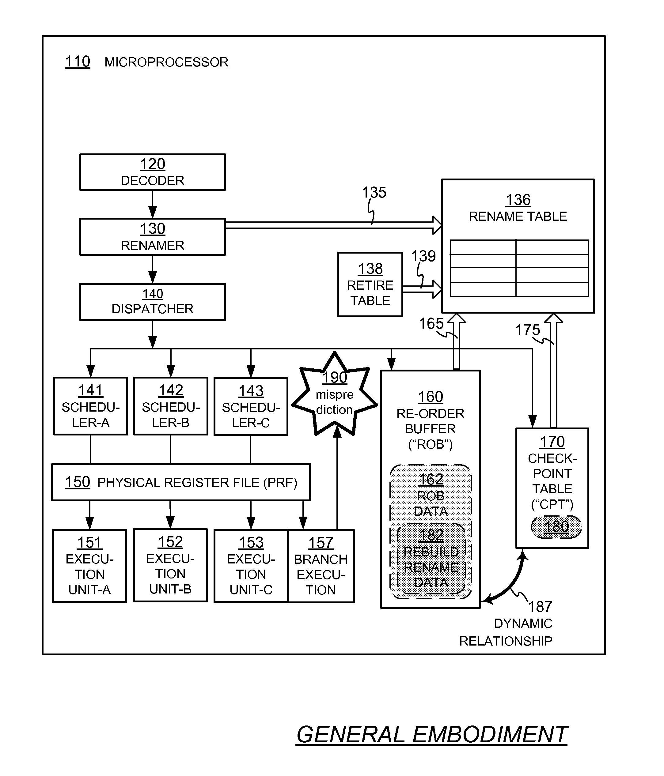
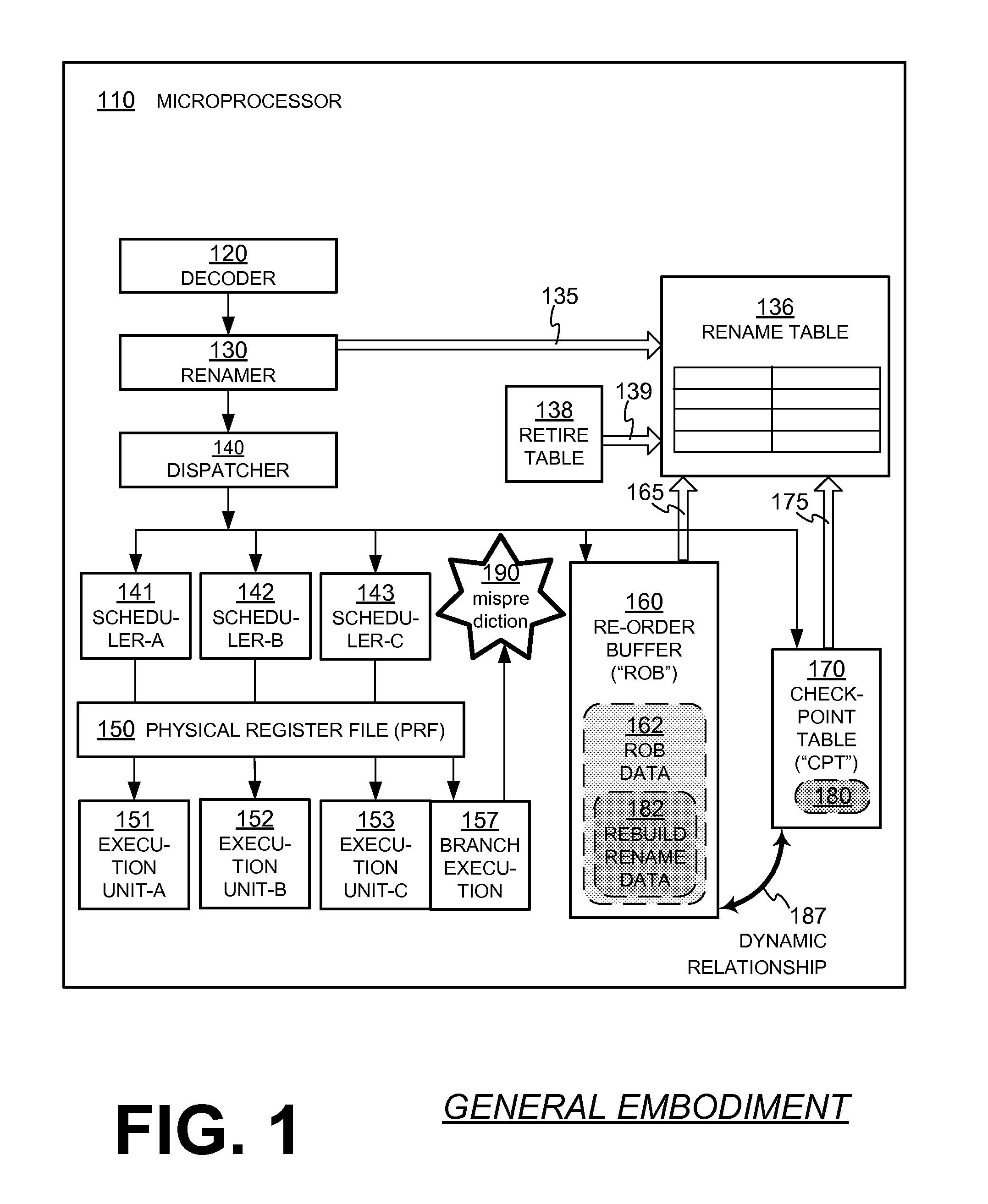
[0024]FIG. 1 is a diagram of components of a microprocessor 110 made according to example embodiments. Microprocessor 110 includes a decoder 120 for receiving instructions, and for decoding these instructions into micro-operations, which are also known as micro-ops.

[0025]Microprocessor 110 also includes one or more execution units for executing the micro-ops. In FIG. 1, three execution units are shown, namely Execution Unit-A 151, Execution Unit-B 152 and Execution Unit-C 153, although that number of units is shown by way of example and not of limitation.

[0026]Decoder 120 and Units 151, 152, 153 are part of the so-called pipe, which includes additional components. One such component is a dispatcher 140, provided for ultimately dispatching the micro-ops to the execution units. In the example of FIG. 1, dispatching is first to one of three sc...


PUM


Abstract

Out-of-order CPUs, devices and methods diminish the time penalty from stalling the pipe to rebuild a rename table, such as due to a misprediction. A microprocessor can include a pipe that has a decoder, a dispatcher, and at least one execution unit. A rename table stores rename data, and a check-point table (“CPT”) stores rename data received from the dispatcher. A Re-Order Buffer (“ROB”) stores ROB data, and has a dynamic mapping relationship with the CPT. If the rename table is flushed, such as due to a misprediction, the rename table is rebuilt at least in part by concurrent copying of rename data stored in the CPT, in coordination with walking the ROB.

Description

CROSS-REFERENCE TO RELATED APPLICATIONS[0001]This application may be found to be related to U.S. patent application Ser. No. 13 / 831,522, filed Mar. 14, 2013, by the same inventors, filed by the same assignee on the same day as the instant application.BACKGROUND[0002]This disclosure relates to semiconductor devices, and more particularly to microprocessors that control the operation of electronic devices, plus electronic devices that use such microprocessors.[0003]A microprocessor, also known as a Central Processing Unit (CPU), works by executing instructions. Some instructions result in branching points, where one path of execution can be chosen over another. A microprocessor can have increased speed if it makes a correct speculative prediction about which path will be chosen, and executes in advance instructions along that path. Such CPUs are known as out-of-order CPUs. The speed benefit diminishes, however, when there was a misprediction, and recovery is required.[0004]A challenge...

Claims


Application Information

Patent Timeline
Patent Type & Authority Patents(United States)
IPC IPC(8): G06F9/30G06F9/38
CPCG06F9/30098G06F9/384G06F9/3855G06F9/3863G06F9/3856G06F9/22
Inventor IYENGAR, RAVISANTHANAKRISHNAN, PRARTHNA
Owner SAMSUNG ELECTRONICS CO LTD
Why Eureka
Try Eureka