Flight control test simulator system and method

a test simulator and flight control technology, applied in the field of load testing systems and methods, can solve the problems of increasing test downtime, increasing labor, tools and costs to adjust the spring rate, and complicating testing

Active Publication Date: 2016-09-27
THE BOEING CO
View PDF38 Cites 10 Cited by
  • Summary
  • Abstract
  • Description
  • Claims
  • Application Information

AI Technical Summary

Benefits of technology

[0007]This need for an improved flight control test simulator system and method is satisfied by this disclosure. As discussed in the below detailed description, embodiments of the improved flight control test simulator system and method may provide significant advantages over known systems and methods.

Problems solved by technology

However, existing flight control test simulator testing using such known spring load systems and methods may require that the testing be halted to make physical and / or geometric modifications to the spring load systems in order to change the aerodynamic load condition by modifying the effective spring rate.
Such halting of the testing may result in increased test downtime and increased labor, tools, and costs to adjust the spring rates.
In addition, existing flight control test simulator testing using such known spring load systems and methods may necessitate that test conditions be grouped in specific aerodynamic states which may complicate testing.
Further, existing flight control test simulator testing using such known spring load systems and methods may prevent the execution of test scenarios where aerodynamic loads vary during a test run (i.e., airspeed changing during the test condition).
Moreover, although existing flight control test simulator testing using such known spring load systems and methods provide repeatable loads with little or no hysteresis, they provide no automated system or method of adjusting or modifying the aerodynamic load condition and spring rate during test execution.

Method used


Image

  • Flight control test simulator system and method
  • Flight control test simulator system and method
  • Flight control test simulator system and method

Examples


Embodiment Construction

[0032]Disclosed embodiments will now be described more fully hereinafter with reference to the accompanying drawings, in which some, but not all of the disclosed embodiments are shown. Indeed, several different embodiments may be provided and should not be construed as limited to the embodiments set forth herein. Rather, these embodiments are provided so that this disclosure will be thorough and will fully convey the scope of the disclosure to those skilled in the art.

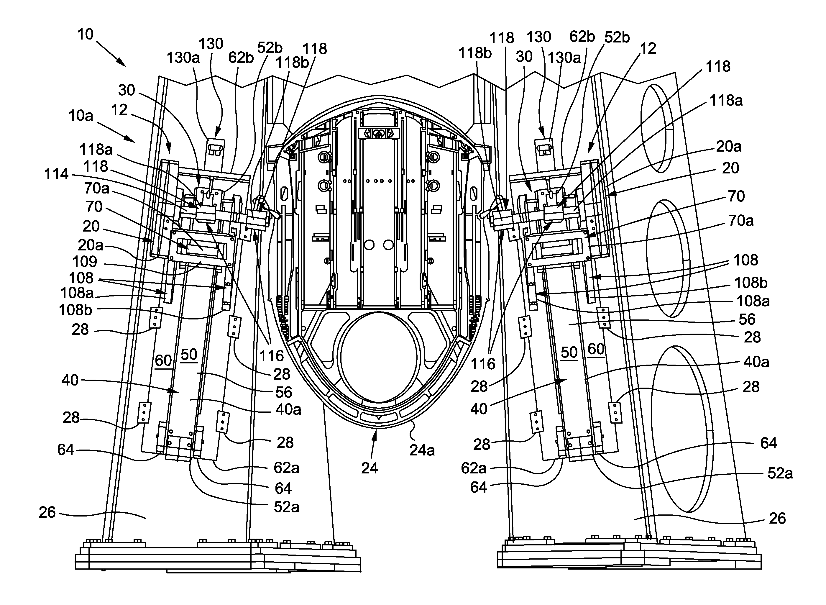
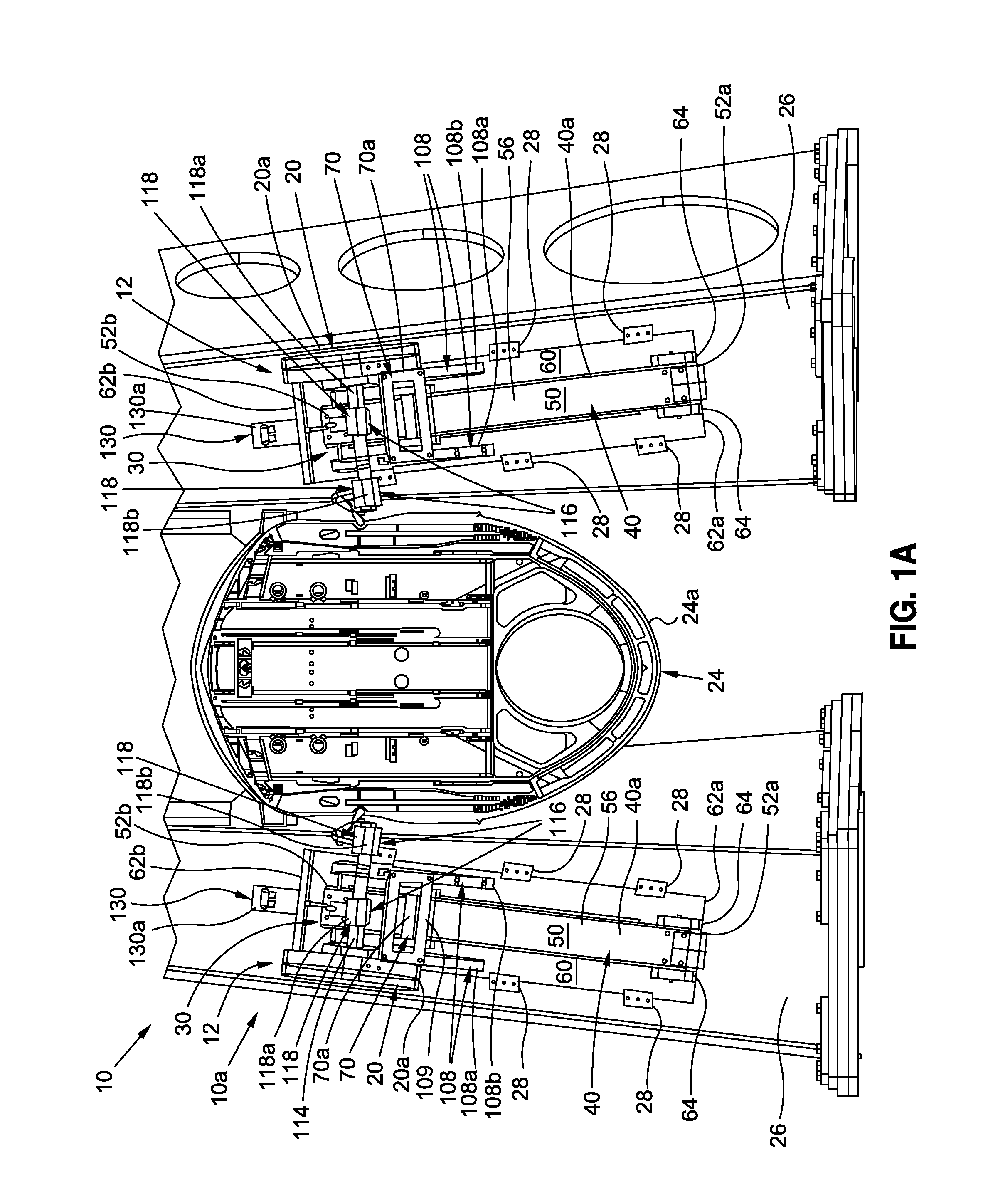
[0033]Now referring to the Figures, FIG. 1A is an illustration of a front perspective view of a flight control test simulator system 10 of the disclosure. In one embodiment of the disclosure, as shown in FIG. 1A, the flight control test simulator system 10 comprises an aircraft flight control test simulator system 10a. FIG. 5 is an illustration of a block diagram of an exemplary embodiment of the flight control test simulator system 10, such as in the form of aircraft flight control test simulator system 10a, of the di...


PUM

PropertyMeasurementUnit
aerodynamic load simulatoraaaaaaaaaa
poweraaaaaaaaaa
Mechanical testingaaaaaaaaaa

Abstract

There is provided a flight control test simulator system and method. The system has a flight control assembly with at least one actuator and with a flight controller configured to actuate the at least one actuator. The system further has an aerodynamic load simulator coupled to the flight control assembly and configured to adjustably induce a simulated continuous aerodynamic load on the flight control assembly. The aerodynamic load simulator has a continuously adjustable spring rate constant assembly configured to adjust the spring rate constant of the induced simulated continuous aerodynamic load over a range of predetermined flight profiles.

Description

BACKGROUND[0001]1) Field of the Disclosure[0002]The disclosure relates generally to load testing systems and methods, and more particularly, to spring load testing systems and methods for performing flight control tests, such as flight control test simulations, on a flight control surface.[0003]2) Description of Related Art[0004]Mechanical testing and integrated systems testing of component parts, or of test specimens of component parts, are often performed in the manufacture of air vehicles, such as aircraft, rotorcraft, spacecraft, and other air vehicles. Such mechanical testing and integrated systems testing provide material property data, such as strength, hardness ductility, and other data about the material as tested under various conditions, such as compression, tension, load and temperature. In turn, such mechanical testing and integrated systems testing provide information relating to the suitability of a material for its intended application. Such information aids in the d...

Claims


Application Information

Patent Timeline
Patent Type & Authority Patents(United States)
IPC IPC(8): G01M5/00G01N3/14G09B9/10
CPCG09B9/10G01M5/005G01M5/0016G01N3/14G01N2203/04G01N3/04
Inventor FINIGAN, JOHN S.EDGERTON, JAMES D.HUGHES, GREGORY J.
Owner THE BOEING CO
Why Eureka
Try Eureka