Multiple device scan chain emulation/debugging

a multi-device, scan chain technology, applied in error detection/correction, program control, instruments, etc., can solve the problems of in-circuit testers generally not being configured, finding damage to the core logic,

Inactive Publication Date: 2010-04-27
WIND RIVER SYSTEMS
View PDF16 Cites 6 Cited by
  • Summary
  • Abstract
  • Description
  • Claims
  • Application Information

AI Technical Summary

Problems solved by technology

A defect, if it occurs, is likely present either in the periphery of the device (leg, bond wire, driver amplifier), in the solder, or in the interconnect between devices.
It is very unusual to find damage to

Method used


Image

  • Multiple device scan chain emulation/debugging
  • Multiple device scan chain emulation/debugging
  • Multiple device scan chain emulation/debugging

Examples


Embodiment Construction

[0024]Referring to the figures set forth in the accompanying drawings, the illustrative embodiments of the present invention will be described in detail hereinbelow. For clarity of exposition, like features shown in the accompanying drawings shall be indicated with like reference numerals and similar features as shown in alternate embodiments in the Drawings shall be indicated with similar reference numerals.

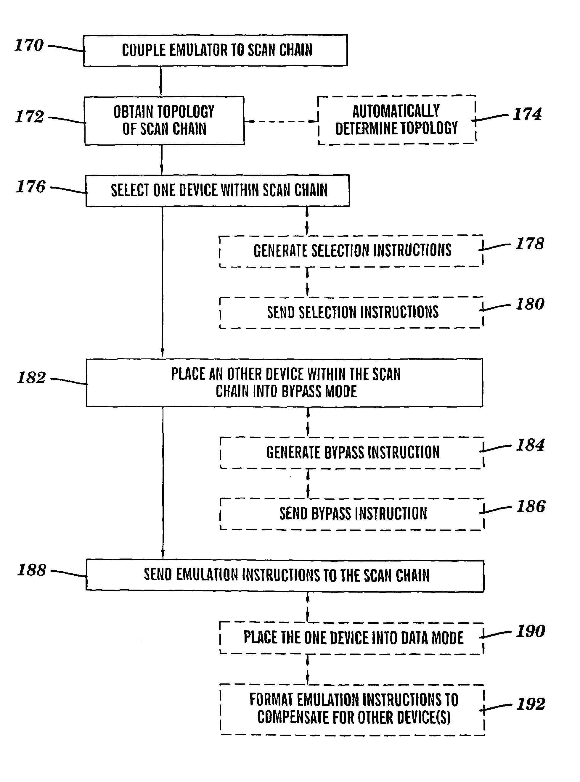
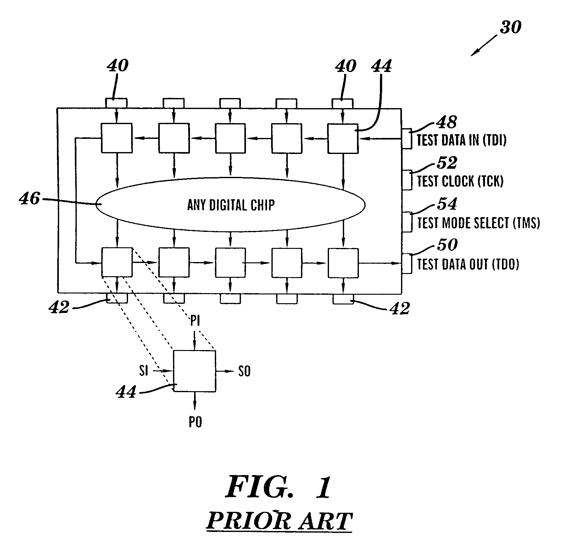
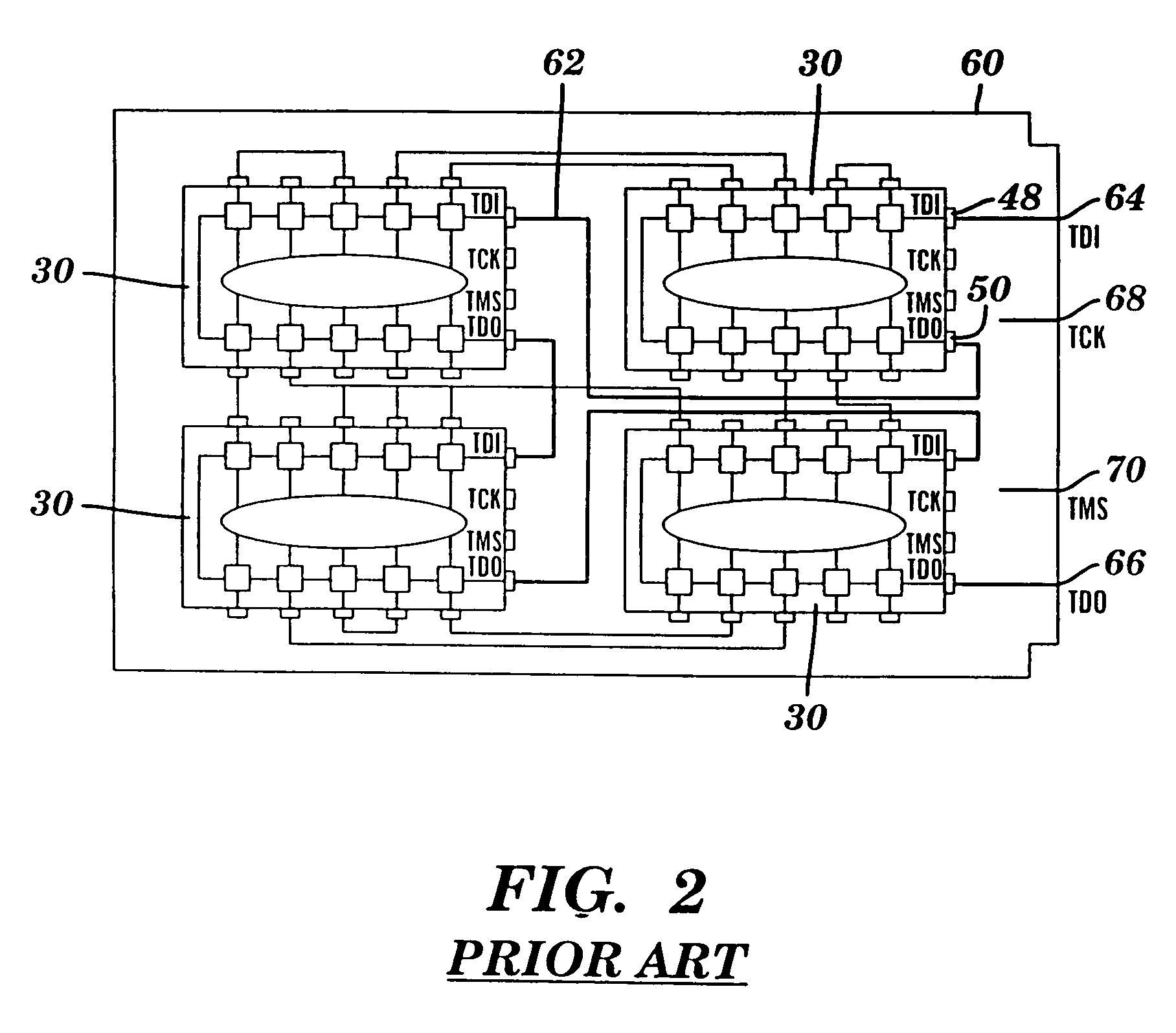
[0025]Embodiments of the present invention include an emulator 10 and software therefor, which enables devices on a multiple device scan chain to be individually targeted for emulation / debugging operations. Particular embodiments of the present invention include JTAG compliant instructions that utilize boundary scan input and output cells to selectively bypass individual devices in the serial scan chain, to enable one or more selected devices to be coupled through the scan chain to the emulator / debugger 110. Examples of JTAG enabled (also referred to as JTAG compliant) devices t...


PUM


Abstract

A method and system is provided for emulating individual JTAG devices in a multiple device boundary scan chain. The method includes coupling an emulator to the scan chain, and obtaining the topology of the scan chain. One device within the scan chain is then selected, and at least one other device within the scan chain is placed into bypass mode. Emulation instructions are sent to the scan chain, so that the emulation instructions bypass the at least one other device and are executed by the one device.

Description

RELATED APPLICATION[0001]This application is a continuation of U.S. Non-Provisional application Ser. No. 09 / 921,250, Filed Aug. 2, 2001, now U.S. Pat. No. 6,886,110, which claims the benefit of U.S. Provisional Application Ser. No. 60 / 252,316, filed Nov. 21, 2000.BACKGROUND[0002]Since the mid-1970s, the structural testing of loaded printed circuit boards (PCBs) has relied very heavily on the use of the so-called in-circuit “bed-of-nails” technique (FIG. 1). This method of testing makes use of a fixture containing a bed-of-nails to access individual devices on the board through test lands laid into the copper interconnect, or other convenient contact points. Testing then generally proceeds in two phases: the power-off tests followed by power-on tests.[0003]Power-off tests check the integrity of the physical contact between nail and the on-board access point. They then may carry out open and shorts tests based on impedance measurements. Power-on tests apply stimulus to a chosen device...

Claims


Application Information

Patent Timeline
IPC IPC(8): G06F9/455G06F11/00G01R31/317G01R31/3185
CPCG01R31/2815G01R31/318536G01R31/31705G01R31/318533
Inventor O'BRIEN, JAMES J.
Owner WIND RIVER SYSTEMS
Why Eureka
Try Eureka