Analytical cell

an analytical cell and cell technology, applied in the field of analytical cells, can solve the problems of difficult selective analysis of only the current generated in the electrode reaction, difficult to accurately observe the electrode reaction of the analysis subject, etc., and achieve the effect of preventing short-circuiting, facilitating and efficient acquisition, and facilitating and efficient us

Active Publication Date: 2016-09-27
HONDA MOTOR CO LTD
View PDF4 Cites 8 Cited by
  • Summary
  • Abstract
  • Description
  • Claims
  • Application Information

AI Technical Summary

Benefits of technology

[0012]A principal object of the present invention is to provide an analytical cell capable of inhibiting or suppressing side reactions on a negative electrode collector and a positive electrode collector, thereby enabling highly accurate analysis of electrode reactions of a negative electrode active material and a positive electrode active material.
[0022]Therefore, side reactions, which are different from analysis subject electrode reactions, can be inhibited on the collector surface, and products of such side reactions can be prevented from becoming attached to the collector surface. Thus, the electrolytic solution or a supporting salt contained therein can be prevented from being consumed in the side reactions, and the electrode reactions can be carried out effectively. In addition, because such side reactions can be inhibited, currents generated in the side reactions can be reduced, and currents generated in the electrode reactions can easily be analyzed.
[0024]In the above analytical cell, the negative electrode active material, the negative electrode collector, the positive electrode active material, and the positive electrode collector may all be formed on the transmission membrane in the first holder. In this case, during production of the analytical cell, the steps of forming the collectors and of forming the lyophobic part thereon can be carried out using only the first holder. Therefore, the analytical cell can be obtained easily and efficiently using a simple production process.
[0025]In the above analytical cell, the negative electrode active material and the negative electrode collector may be formed on the transmission membrane in the first holder, and the positive electrode active material and the positive electrode collector may be formed on the transmission membrane in the second holder. In this case, the negative electrode active material and the positive electrode active material are formed on each of the first holder and the second holder, respectively. Therefore, even if the negative electrode active material and the positive electrode active material are disposed in a small space, the negative electrode active material and the positive electrode active material are not arranged excessively close to each other, and can be kept out of contact with each other. Consequently, the negative electrode active material and the positive electrode active material can be effectively prevented from short-circuiting.
[0026]In the above analytical cell, preferably, a lyophilic part having an affinity for the electrolytic solution is formed in vicinity of at least one of the negative electrode active material and the positive electrode active material on a surface in contact with the electrolytic solution of the transmission membrane. The lyophilic part can be formed by subjecting a transmission membrane surface to a lyophilization treatment. The electrolytic solution exhibits a smaller contact angle on the transmission membrane surface with the lyophilic part than without it. In other words, the electrolytic solution exhibits a larger contact area on the transmission membrane surface with the lyophilic part. Thus, the electrolytic solution can more easily be located in the vicinity of the active material in the overlapping portion. Consequently, the electrode reactions, which are the subject of analysis, can more effectively be carried out and analyzed with high accuracy.

Problems solved by technology

Therefore, in the case that currents are generated in both of the electrode reactions and the side reaction, it is difficult to selectively analyze only the current generated in the electrode reactions.
Thus, in the case that the side reaction is caused on collector surfaces that are in contact with the electrolytic solution, it is difficult to accurately observe the electrode reactions of the analysis subjects.

Method used


Image

  • Analytical cell
  • Analytical cell
  • Analytical cell

Examples


first embodiment

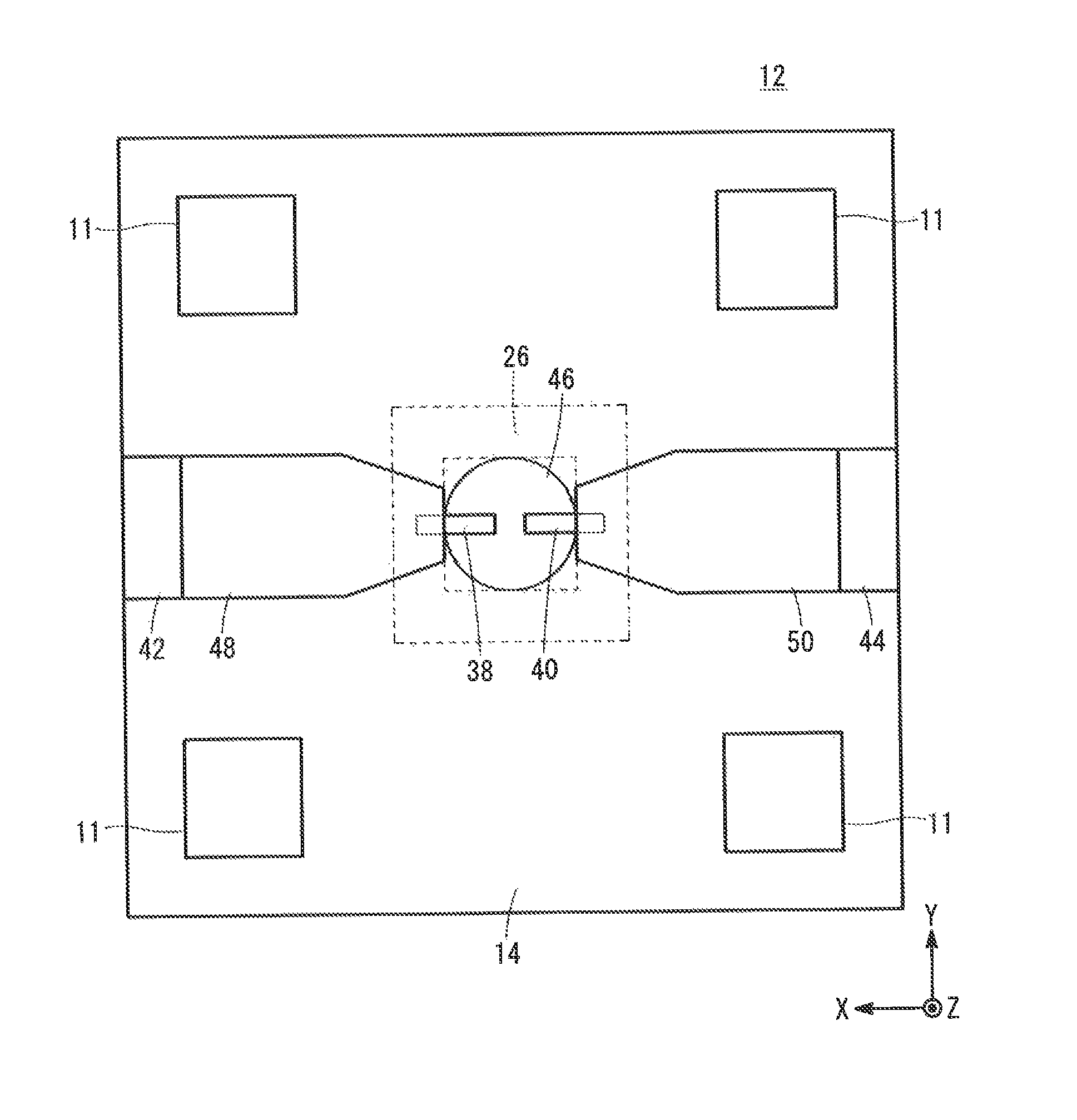
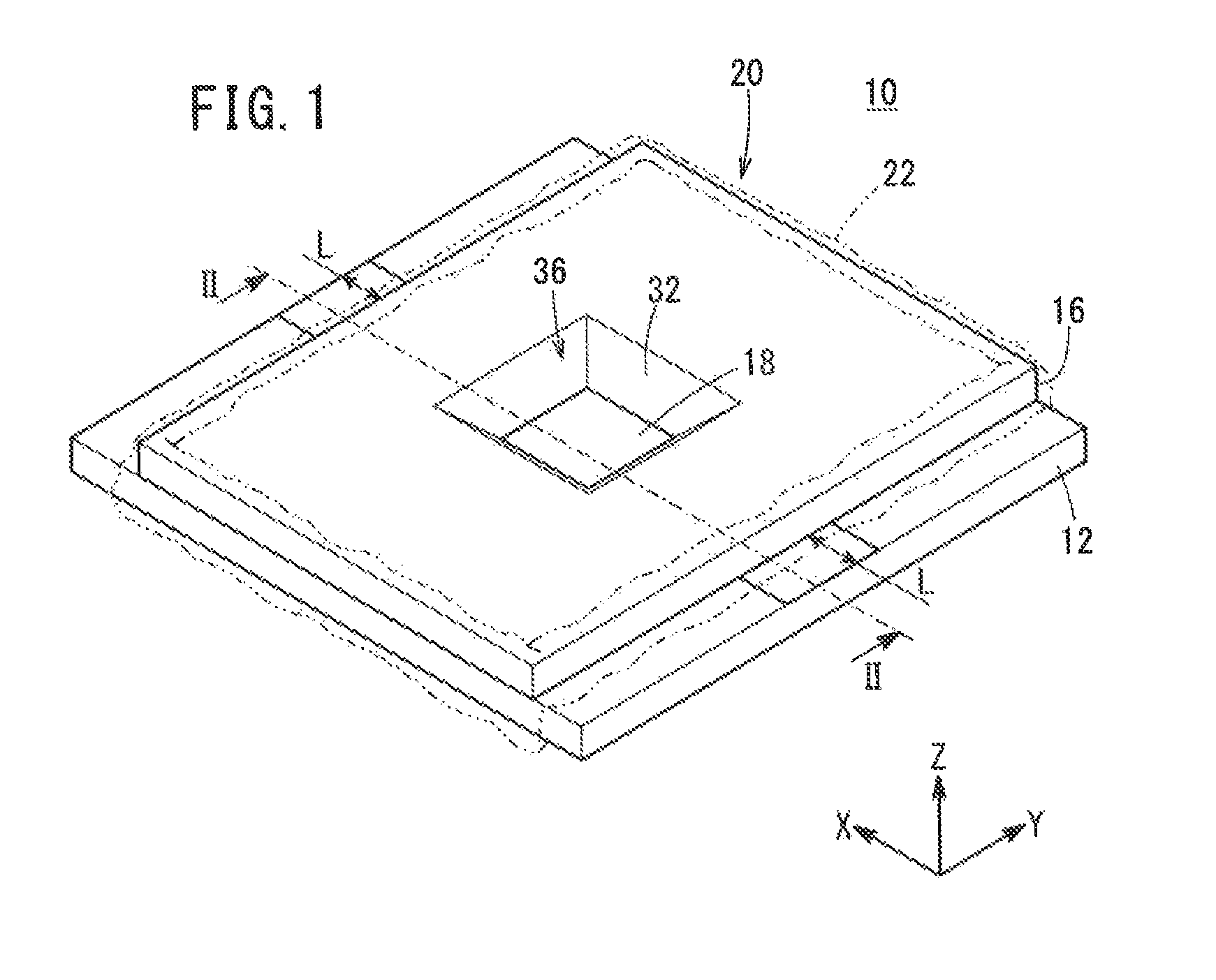
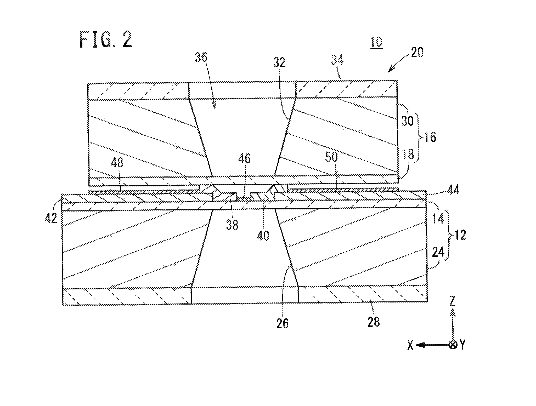
[0069]An analytical cell 10 according to a first embodiment will be described below with reference to FIGS. 1 to 4. FIG. 1 is an overall schematic perspective view of the analytical cell 10. FIG. 2 is a cross-sectional view taken along line II-II of FIG. 1 in the direction of the arrows. FIG. 3 is a plan view of a transmission membrane 14 side of a first holder 12 in the analytical cell 10. FIG. 4 is a plan view of a transmission membrane 18 side of a second holder 16 in the analytical cell 10. To facilitate understanding, in the following description, the X-axis, Y-axis, and Z-axis directions shown in FIGS. 1 to 4 are defined as width, depth, and height directions, respectively. In addition, in the X-axis, Y-axis, and Z-axis directions, the tip of each arrow is defined as one end, and the base end of the arrow is defined as another end.

[0070]The analytical cell 10 contains the first holder 12 and the second holder 16 stacked with an electrolytic solution interposed therebetween. Mo...

second embodiment

[0121]An analytical cell 88 according to a second embodiment will be described below with reference to FIGS. 36 to 39. FIG. 36 is an overall schematic perspective view of the analytical cell 88. FIG. 37 is a cross-sectional view of the analytical cell 88 taken along line XXXVII-XXXVII of FIG. 36 in the direction of the arrows. FIG. 38 is a plan view of a transmission membrane 14 side of a first holder 90 in the analytical cell 88. FIG. 39 is a plan view of a transmission membrane 18 side of a second holder 92 in the analytical cell 88. The components shown in FIGS. 36 to 39, which have equal or similar functions and effects to those shown in FIGS. 1 to 35C, are denoted by the same reference numerals, and detailed explanations of such features are omitted.

[0122]The analytical cell 88 contains the first holder 90 and the second holder 92, instead of the first holder 12 and the second holder 16 that are used in the analytical cell 10. Further, the first holder 90 contains a substrate 9...


PUM

PropertyMeasurementUnit
sizeaaaaaaaaaa
permeabilityaaaaaaaaaa
thicknessaaaaaaaaaa

Abstract

An analytical cell includes a first holder and a second holder. The first holder and the second holder each contain a substrate including a through-hole and a transmission membrane having an electron beam permeability. The through-hole is covered with the transmission membrane. The first holder and the second holder are stacked to form an overlapping portion such that the transmission membranes face toward each other. A negative electrode active material and a positive electrode active material, which are arranged at a distance from each other and are in contact, respectively, with an electrolytic solution, are connected electrically to a negative electrode collector and a positive electrode collector, respectively, in the overlapping portion. A lyophobic part having no affinity for the electrolytic solution is formed on at least one of the negative electrode collector and the positive electrode collector.

Description

CROSS-REFERENCE TO RELATED APPLICATION[0001]This application is based upon and claims the benefit of priority from Japanese Patent Application No. 2014-166794 filed on Aug. 19, 2014, the contents of which are incorporated herein by reference.BACKGROUND OF THE INVENTION[0002]1. Field of the Invention[0003]The present invention relates to an analytical cell suitable for use, for example, in performing an electrode reaction analysis in relation to analytical equipment.[0004]2. Description of the Related Art[0005]As is well known, in an electric cell, a negative electrode active material and a positive electrode active material undergo electrode reactions in a charge-discharge process. In recent years, such electrode reactions have been analyzed during the charge-discharge process using analytical equipment. For example, an analytical cell, which can be observed by a transmission electron microscope (TEM), has been proposed in In-situ Electron Microscopy of Electrical Energy Storage Mat...

Claims


Application Information

Patent Timeline
Patent Type & Authority Patents(United States)
IPC IPC(8): H01J37/20H01M4/02H01M10/058
CPCH01J37/20H01J2237/2007H01J2237/2602H01J2237/2802H01J2237/2003Y02P70/50
Inventor FUJIWARA, YOSHIYAKURIYAMA, NARIAKIMAEBASHI, TAKANORIKAWAI, MITSUMOTO
Owner HONDA MOTOR CO LTD
Why Eureka
Try Eureka