Analytical cell

Inactive Publication Date: 2015-10-15
HONDA MOTOR CO LTD
View PDF4 Cites 3 Cited by
  • Summary
  • Abstract
  • Description
  • Claims
  • Application Information

AI Technical Summary

Benefits of technology

[0019]In the analytical cell of the present invention, the isolation membrane for avoiding contact with the electrolytic solution is formed on at least one of the negative electrode collector and the positive electrode collector in the overlapping portion. Therefore, side reactions, which are different from the electrode reactions of the negative electrode active material and the positive electrode active material, can be suppressed on the negative electrode collector and the positive electrode collector. Consequently, the electrode reactions of the analysis subjects can be highly accurately analyzed by observing the negative electrode active material, the positive electrode active material, or the like while transmitting the electron beam through the analytical cell.
[0020]In the above analytical cell, each of the negative electrode collector and the positive electrode collector may have a layer structure with one surface contacting the first holder and the other surface having the isolation membrane. In this case, in production of the analytical cell, the negative electrode collector and the positive electrode collector may be formed only on the first holder. The one surface of the negative electrode collector and the one surface of the positive electrode collector are in contact with the first holder (e.g., the transmission membrane) and are not in contact with the electrolytic solution. Therefore, the contact of the negative electrode collector and the positive electrode collector with the electrolytic solution can be avoided by forming the isolation membranes only on the other surfaces. Consequently, the analytical cell can be easily and efficiently obtained by a simple production process.
[0021]In the above analytical cell, the negative electrode collector may have a layer structure with one surface contacting the first holder and the other surface having the isolation membrane, and the positive electrode collector may have a layer structure with one surface contacting the second holder and the other surface having the isolation membrane. In this case, the negative electrode active material and the posit

Problems solved by technology

In this case, it is difficult to accurately observ

Method used


Image

  • Analytical cell
  • Analytical cell
  • Analytical cell

Examples


Example

First Embodiment

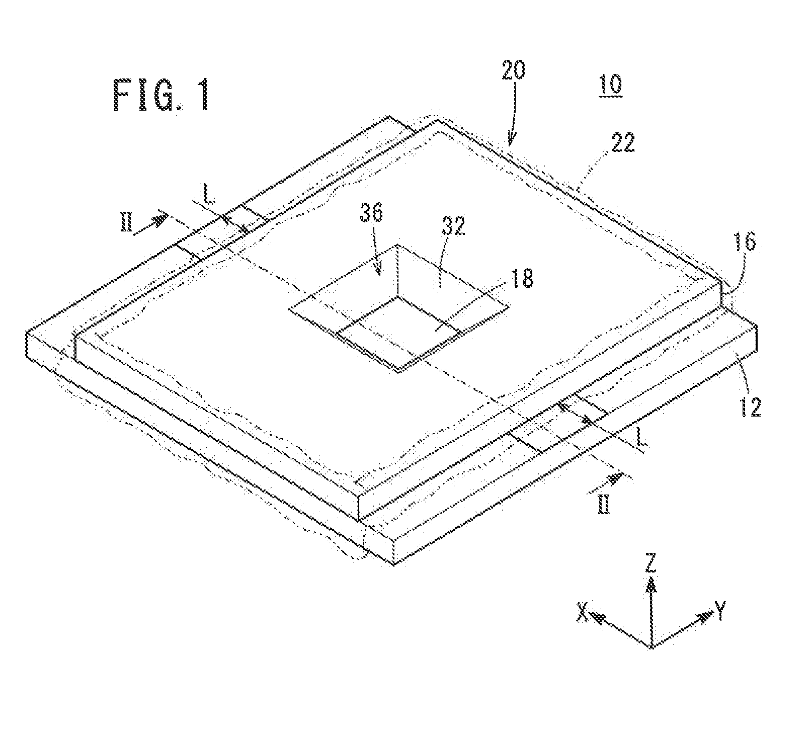
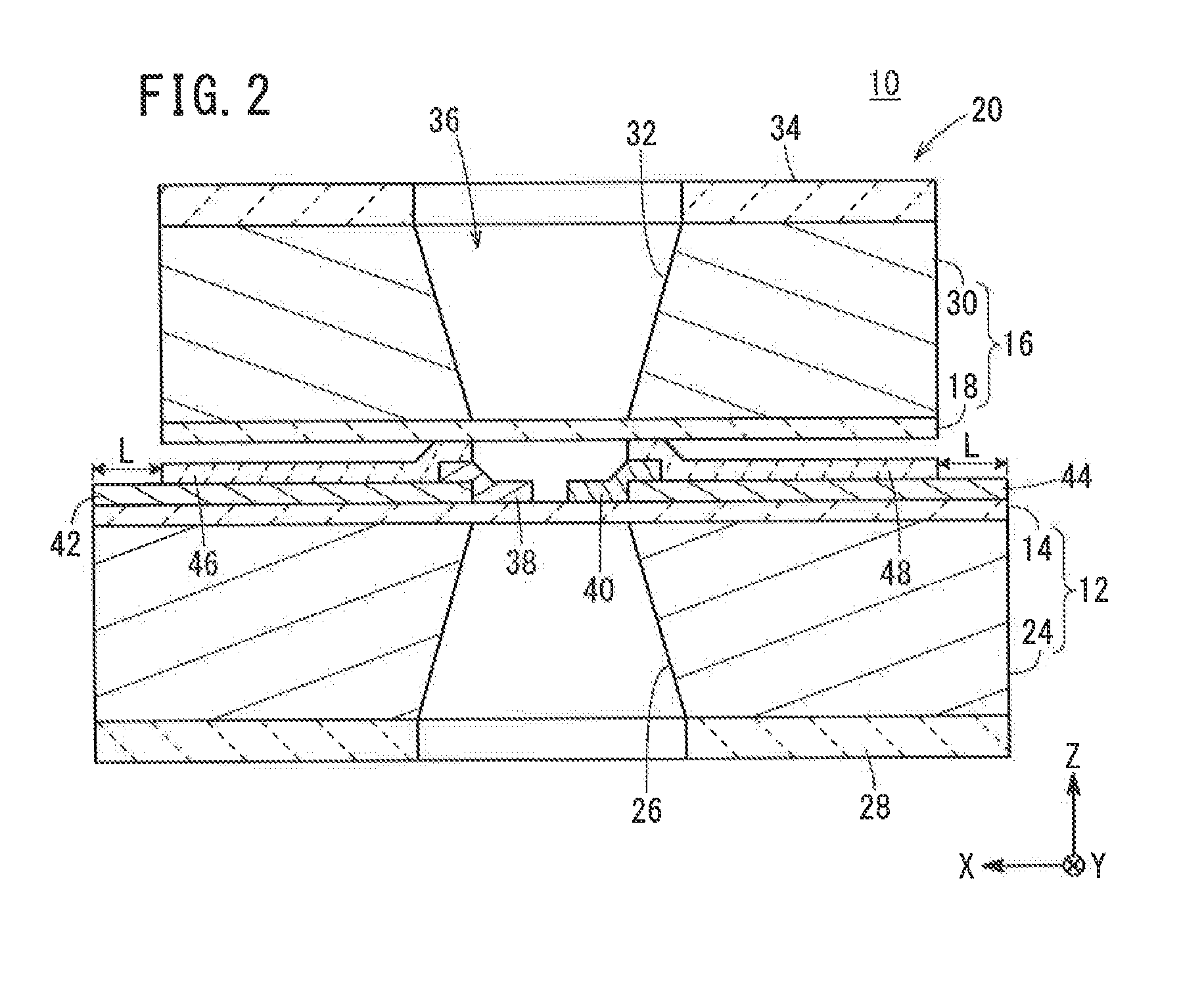
[0066]An analytical cell 10 according to a first embodiment will be described below with reference to FIGS. 1 to 4. FIG. 1 is an overall schematic perspective view of the analytical cell 10. FIG. 2 is a cross-sectional view taken along the line II-II in FIG. 1 in the direction of the arrows. FIG. 3 is a plan view of a transmission membrane (electron beam permeable membrane or electron beam transparent membrane) 14 side of a first holder 12 in the analytical cell 10. FIG. 4 is a plan view of a transmission membrane (electron beam permeable membrane or electron beam transparent membrane) 18 side of a second holder 16 in the analytical cell 10. To facilitate understanding, the X-axis, Y-axis, and Z-axis directions shown in FIGS. 1 to 4 are defined as the width, depth, and height directions respectively in the following description. In addition, in the X-axis, Y-axis, and Z-axis directions, the tip of the arrow is defined as one end, and the base end of the arrow is defi...

Example

Second Embodiment

[0111]An analytical cell 88 according to a second embodiment will be described below with reference to FIG. 33. FIG. 33 is a cross-sectional view of the analytical cell 88 taken in the same direction as FIG. 2. The components in FIG. 33, equal or similar in functions and effects to those in FIGS. 1 to 32C, are denoted by the same reference numerals, and detailed explanations thereof are omitted.

[0112]The analytical cell 88 contains isolation membranes 90, 92 instead of the isolation membranes 46, 48 in the analytical cell 10. The isolation membranes 90, 92 contain a substance having electrically insulating and electron beam permeable properties. Preferred examples of such substances include silicon nitride.

[0113]The isolation membranes 90, 92 are different from the isolation membranes 46, 48 in that the other end of the isolation membrane 90 and the one end of the isolation membrane 92 reach the inside of the observation window 36. Thus, each of the isolation membra...

Example

Third Embodiment

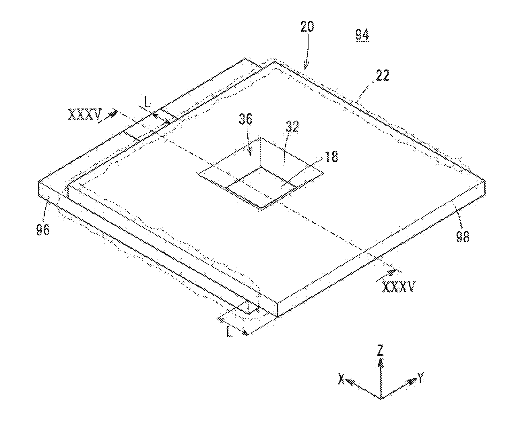
[0116]An analytical cell 94 according to a third embodiment will be described below with reference to FIGS. 34 to 37. FIG. 34 is an overall schematic perspective view of the analytical cell 94. FIG. 35 is a cross-sectional view of the analytical cell 94 of FIG. 34 taken along the line XXXV-XXXV in the direction of the arrows. FIG. 36 is a plan view of a transmission membrane 14 side of a first holder 96 in the analytical cell 94. FIG. 37 is a plan view of a transmission membrane 18 side of a second holder 98 in the analytical cell 94. The components in FIGS. 34 to 37, equal or similar in functions and effects to those in FIGS. 1 to 33, are denoted by the same reference numerals, and detailed explanations thereof are omitted.

[0117]The analytical cell 94 contains the first holder 96 and the second holder 98 instead of the first holder 12 and the second holder 16 in the analytical cell 10. The first holder 96 contains a substrate 100 instead of the substrate 24, and the...


PUM


Abstract

An analytical cell includes first and second holders. The first and second holders each contain a substrate having a through-hole and a transmission membrane with an electron beam permeability so as to cover the through-hole. The first and second holders are stacked to form an overlapping portion such that the transmission membranes face each other. The through-holes face each other across the transmission membranes to form an observation window. Negative and positive electrode active materials are separated from each other and contact the electrolytic solution in the observation window. The negative and positive electrode active materials are electrically connected to negative and positive electrode collectors, respectively, in the overlapping portion. At least one of the negative and positive electrode collectors has an electrically insulating isolation membrane for avoiding contact with the electrolytic solution.

Description

CROSS-REFERENCE TO RELATED APPLICATION[0001]This application is based upon and claims the benefit of priority from Japanese Patent Application No. 2014-080427 filed on Apr. 9, 2014, the contents of which are incorporated herein by reference.BACKGROUND OF THE INVENTION[0002]1. Field of the Invention[0003]The present invention relates to an analytical cell suitable for use, e.g., in an electrode reaction analysis in an analytical equipment.[0004]2. Description of the Related Art[0005]As is well known, in an electric cell, a negative electrode active material and a positive electrode active material undergo electrode reactions in the charge-discharge process. In recent years, the electrode reactions have been analyzed during the charge-discharge process using analytical equipment. For example, an analytical cell that can be observed by a transmission electron microscope (TEM) has been proposed in In-situ Electron Microscopy of Electrical Energy Storage Materials [online], 2014, Retriev...

Claims


Application Information

Patent Timeline
IPC IPC(8): H01J37/20
CPCH01J2237/2007H01J37/20Y02P70/50
Inventor KURIYAMA, NARIAKIFUJIWARA, YOSHIYA
Owner HONDA MOTOR CO LTD
Why Eureka
Try Eureka