Supercharge Your Innovation With Domain-Expert AI Agents!

Polishing pad with porous interface and solid core, and related apparatus and methods

a technology of porous interface and solid core, applied in the direction of lapping tools, manufacturing tools, lapping machines, etc., can solve the problems of low removal rate, high removal rate of polishing pads made of hard materials, and many scratches

Active Publication Date: 2016-10-11
CMC MATERIALS LLC
View PDF19 Cites 0 Cited by
  • Summary
  • Abstract
  • Description
  • Claims
  • Application Information

AI Technical Summary

Benefits of technology

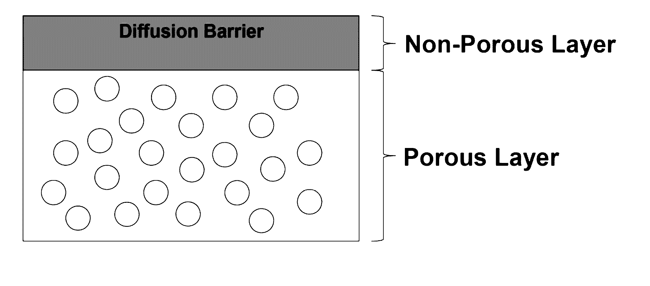
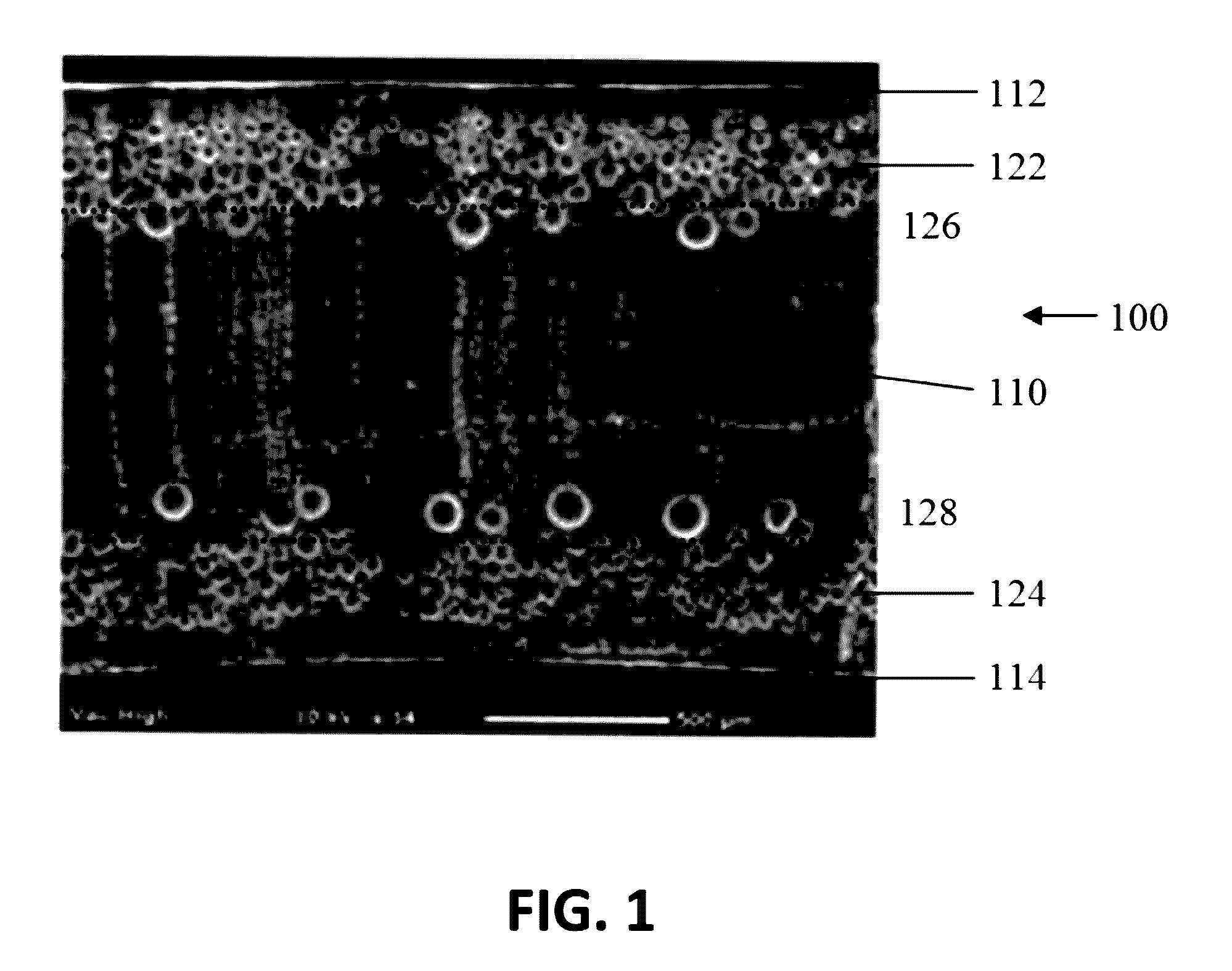
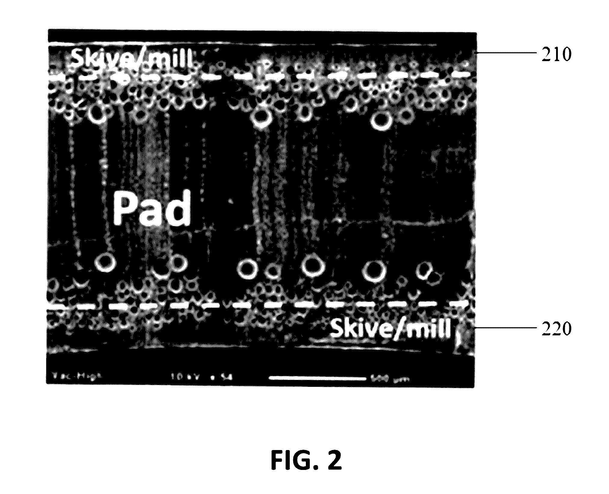
The invention provides a polishing pad for chemical-mechanical polishing that has a porous surface region directly contacting a non-porous core region. The polishing pad is monolithic, meaning it is made from a single piece of material. The core region is harder than the porous surface region, which makes it easier to polish the workpiece. The polishing pad can also have a chemical-mechanical polishing composition between the pad and the workpiece. The method of making the polishing pad involves providing a monolithic polymer sheet with two surfaces and introducing inert gas under conditions that form a porous surface region adjacent to one of the surfaces and a non-porous core region. The invention provides a polishing pad that has improved polishing efficiency and produces better surface quality.

Problems solved by technology

Polishing pads made of harder materials exhibit high removal rates and have long useful pad life, but tend to produce numerous scratches on substrates being polished.
Polishing pads made of softer materials exhibit low scratching of substrates, but tend to exhibit lower removal rates and have shorter useful pad life.
Accordingly, there remains a need in the art for polishing pads that provide effective removal rates and have extended pad life, and also produce limited scratching.

Method used


Image

  • Polishing pad with porous interface and solid core, and related apparatus and methods
  • Polishing pad with porous interface and solid core, and related apparatus and methods
  • Polishing pad with porous interface and solid core, and related apparatus and methods

Examples


example 1

[0052]This example illustrates the preparation of inventive polishing pads (polishing pads 1A-1D) and comparative polishing pads (polishing pads 1E-1T). The scanning electron micrographs (SEMs) depicted by the lettering (a)-(t) in FIG. 5 correspond to polishing pads 1A-1T, respectively, in this example. All of the polishing pads were prepared from an extruded thermoplastic polyurethane (TPU) having a hardness of 60D on the Shore D hardness scale as measured according to ASTM D22400-00. The description below relative to inventive polishing pads 1A-1D illustrates process conditions that favor the formation of solid core-porous interface dual morphology using gassing temperature and saturation time as control variables in accordance with embodiments of the invention. In contrast, the description relative to comparative polishing pads 1E-1J illustrate conditions that do not favor the formation of solid core-porous interface morphology, and the description relative to comparative polishi...

example 2

[0060]This example illustrates the preparation of inventive polishing pads (polishing pads 2A-2F) and comparative polishing pads (polishing pads 2G-2T). The scanning electron micrographs (SEMs) depicted by the lettering (a)-(t) in FIG. 6 correspond to polishing pads 2A-2T, respectively, in this example. All of the polishing pads were prepared from an extruded thermoplastic polyurethane (TPU) having a hardness of 60D on the Shore D hardness scale, as measured according to ASTM D22400-00. The description below relative to inventive polishing pads 2A-2F illustrates process conditions that favor the formation of a solid core-porous interface dual morphology using gassing temperature and saturation time as control variables in accordance with embodiments of the invention. In contrast, the description relative to comparative polishing pads 2G-2I illustrates conditions that do not favor the formation of a solid core-porous interface morphology, and the description relative to comparative p...


PUM

PropertyMeasurementUnit
temperatureaaaaaaaaaa
pressureaaaaaaaaaa
temperatureaaaaaaaaaa

Abstract

Disclosed is a polishing pad for chemical-mechanical polishing. The polishing pad has a porous interface and a substantially non-porous bulk core. Also disclosed are related apparatus and methods for using and preparing the polishing pad.

Description

BACKGROUND OF THE INVENTION[0001]Chemical-mechanical polishing (“CMP”) processes are used in the manufacturing of microelectronic devices to form flat surfaces on semiconductor wafers, field emission displays, and many other microelectronic substrates. For example, the manufacture of semiconductor devices generally involves the formation of various process layers, selective removal or patterning of portions of those layers, and deposition of yet additional process layers above the surface of a semiconducting substrate to form a semiconductor wafer. The process layers can include, by way of example, insulation layers, gate oxide layers, conductive layers, and layers of metal or glass, etc. It is generally desirable in certain steps of the wafer process that the uppermost surface of the process layers be planar, i.e., flat, for the deposition of subsequent layers. CMP is used to planarize process layers wherein a deposited material, such as a conductive or insulating material, is poli...

Claims


Application Information

Patent Timeline
Patent Type & Authority Patents(United States)
IPC IPC(8): B24B37/24H01L21/306B24B37/04C08J9/12C08J9/00B24B37/22
CPCB24B37/24B24B37/22B24B37/042C08J9/122C08J2375/04C08J2207/00C08J2201/032C08J2203/06C08J2205/044C08J2205/052C08J2300/22C08J2300/26
Inventor VACASSY, ROBERTFOTOU, GEORGE
Owner CMC MATERIALS LLC
Features
  • R&D
  • Intellectual Property
  • Life Sciences
  • Materials
  • Tech Scout
  • Unparalleled Data Quality
  • Higher Quality Content
  • 60% Fewer Hallucinations
Learn More