Powered cargo rack for tall vehicles

a technology for tall vehicles and cargo racks, applied in vehicle components, transportation and packaging, supplementary fittings, etc., can solve the problems of minimal number of setups and teardowns, and achieve the effect of facilitating cargo unloading

Inactive Publication Date: 2016-10-11
API ENG
View PDF41 Cites 7 Cited by
  • Summary
  • Abstract
  • Description
  • Claims
  • Application Information

AI Technical Summary

Benefits of technology

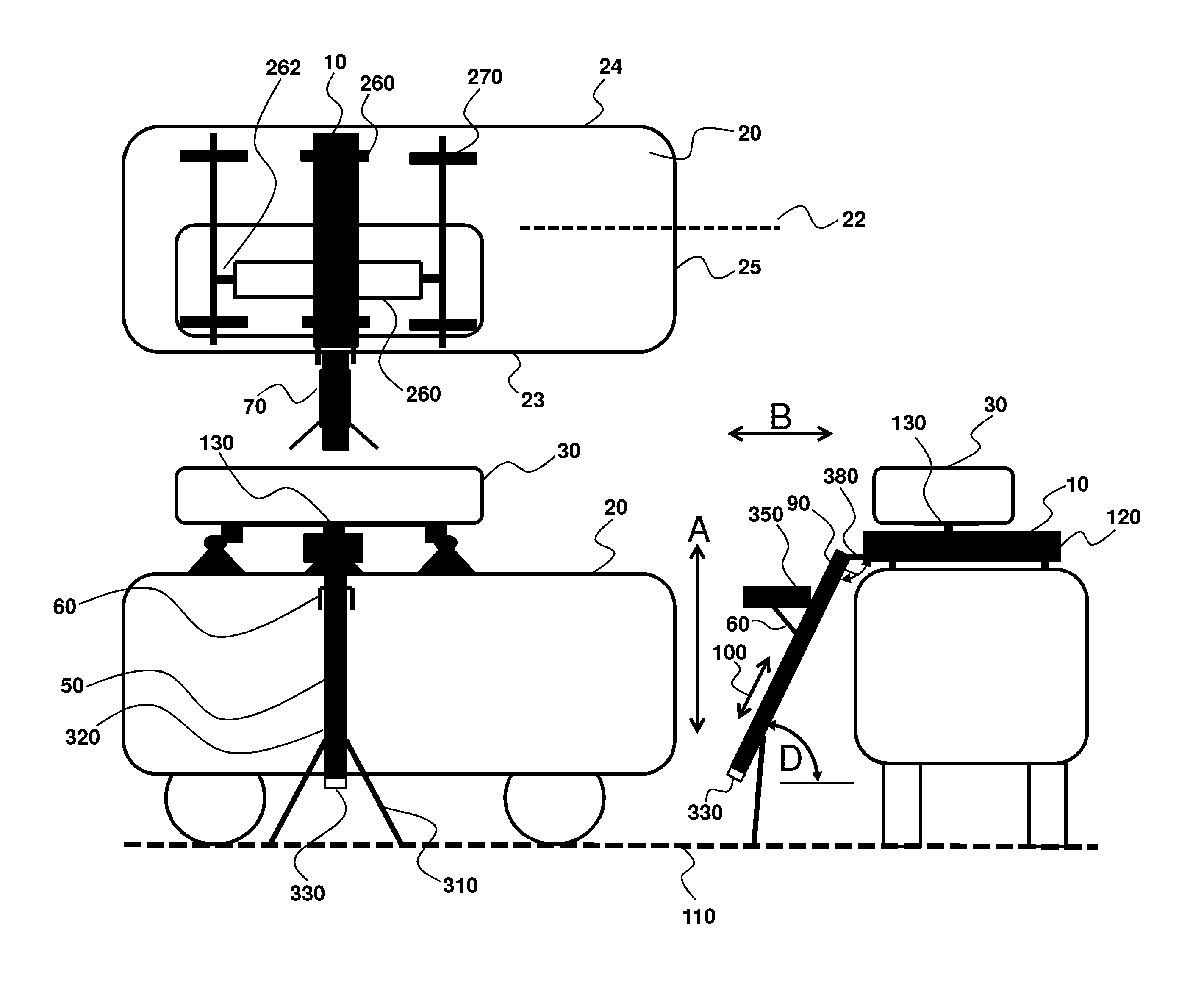
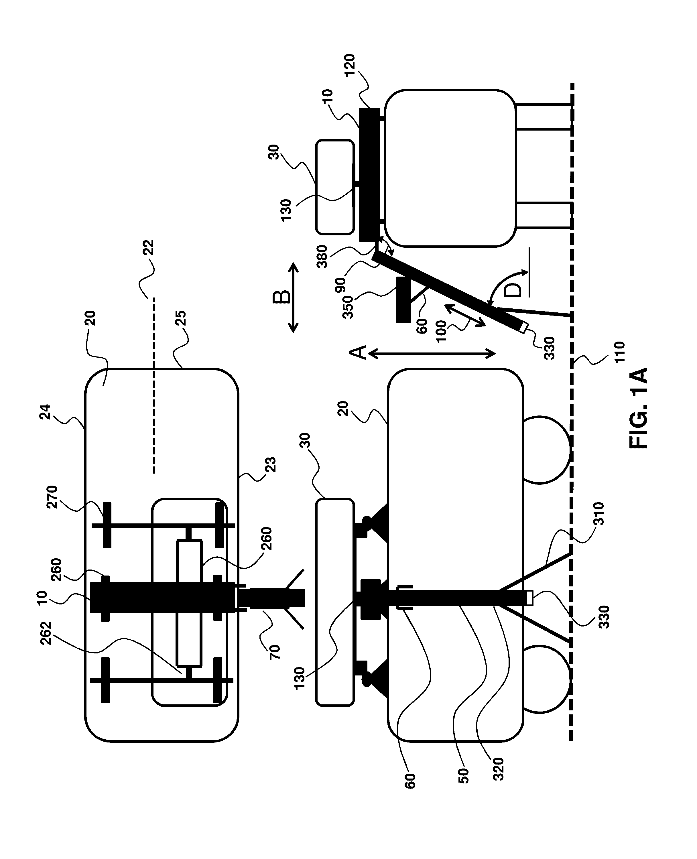
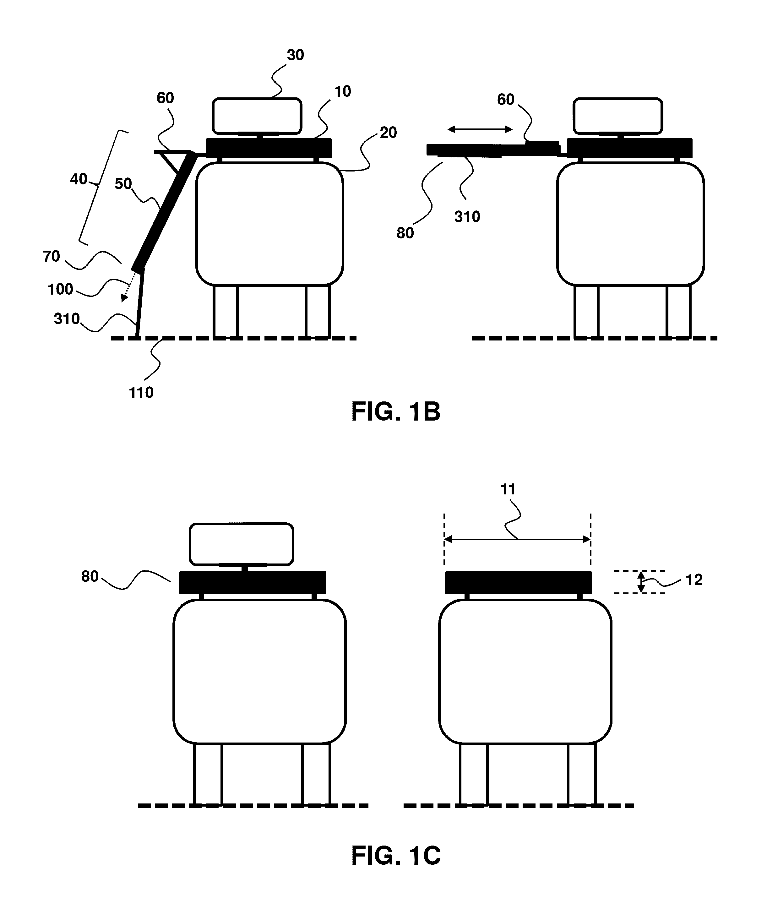
[0007]During all operation and movement, the cargo load supported by the device remains parallel to the ground so that ease of loading / unloading is maximized. At roof height the cargo motion onto and off of the roof is essentially linear and essentially parallel to the ground. Cargo motion between roof height and the near ground level loading / unloading position is also essentially linear and near vertical. In this manner, the majority of the cargo load is supported on the ground during loading / unloading, thus ensuring vehicle loads are minimized. One particular advantage of the devices and methods provided herein is the ability for use of only one powered roof rack while accommodating cargo loads that are not centered on the roof rack. Furthermore, any of the devices and methods provided herein is configured so that all parts may be stowed within a low profile roof mounted package when not in use. Such configuration also results in a setup and teardown with a minimal number of easy to execute steps.
[0022]For aspects where the device is electrically powered, the device further comprises an electric drive connected to the lift assembly to translationally move the foldable cargo slide support along the longitudinal lift member. In this manner, cargo is moved up and down a vertical height between the loading / unloading height and transfer height. The translational connection of the cargo slide platform facilitates a relatively minor user-supplied force to move the cargo toward the roof top for cargo loading. A similar configuration in reverse facilitates cargo unloading from a vehicle roof.

Problems solved by technology

Such configuration also results in a setup and teardown with a minimal number of easy to execute steps.

Method used


Image

  • Powered cargo rack for tall vehicles
  • Powered cargo rack for tall vehicles
  • Powered cargo rack for tall vehicles

Examples


Embodiment Construction

[0041]In general, the terms and phrases used herein have their art-recognized meaning, which can be found by reference to standard texts, journal references and contexts known to those skilled in the art. The following definitions are provided to clarify their specific use in the context of the invention.

[0042]“Operably connected” or “operably receiving” refers to a configuration of elements, wherein an action or reaction of one element affects another element, but in a manner that preserves each element's functionality. For example, a track may operably receive corresponding rollers such that the rollers rotation provides translation motion between an element connected to the rollers and the track. Ground support legs operably connected to a longitudinal lift member refers to the ground support that may provide load distribution to the ground without impacting the ability of the longitudinal lift member to translate the foldable cargo slide support. Similarly, the action of an elec...


PUM


Abstract

Provided are powered roof racks for tall vehicles, configured for cargo loading or unloading near to and parallel to the ground. The cargo is lifted to or lowered from roof height using an electric drive. Cargo motion comprises two separate essentially linear motions. The motion on and off of the roof is linear and essentially horizontal. The motion between roof height and the near ground level loading / unloading position is linear and near vertical. During all operations the load remains parallel to the ground. The majority of cargo load is supported on the ground during loading / unloading. All parts may be stored in a low profile roof mounted package when not in use, and ensures that setup and teardown uses a minimal number of easy to execute steps.

Description

CROSS-REFERENCE TO RELATED APPLICATIONS[0001]This application claims the benefit of priority from U.S. Provisional Patent Application No. 61 / 875,527 filed Sep. 9, 2013, which is hereby incorporated by reference in its entirety to the extent not inconsistent herewith.BACKGROUND OF INVENTION[0002]Provided herein are cargo racks for vehicle roofs and related methods, including for such racks that include mechanization for moving the rack between the roof and a position closer to ground level for easier loading and unloading.[0003]Cargo racks designed to mount on vehicle roofs are widely available commercially. Such commercially available roof top racks, when placed on tall vehicles such as large sport utility vehicles, are difficult to load and unload due to their height above the ground. A wide range of patents attempt to make loading and unloading such racks easier. Many of those patents, e.g. U.S. Pat. Nos. 6,681,970, 6,015,074, involve various mechanizations based on pivoting the l...

Claims


Application Information

Patent Timeline
Patent Type & Authority Patents(United States)
IPC IPC(8): B60R9/042
CPCB60R9/042
Inventor PRESLEY, KENNETH LEE
Owner API ENG
Why Eureka
Try Eureka