Compact space-saving gun silencer

a space-saving, compact technology, applied in the direction of weapons, weapon components, etc., can solve the problems of increased excessive volume of the silencer (suppressor), cumbersome cylinders or tubes, etc., to reduce the sound and flash signature of the host firearm, compact and compact form factor (or length), and the effect of reducing the sound and flash signatur

Active Publication Date: 2016-10-11
CGS TECH LLC
View PDF12 Cites 3 Cited by
  • Summary
  • Abstract
  • Description
  • Claims
  • Application Information

AI Technical Summary

Benefits of technology

[0008]The present invention is a silencer (or suppressor) for a firearm which is intended for reducing the sound and flash signature of the host firearm. The invention overcomes the above-noted and other deficiencies of the prior art by providing a firearm silencer and methods for manufacturing and fastening a silencer onto a firearm that has a very compact reduced form factor (or length) which has significant benefit to the operability and maneuverability of the firearm.
[0009]This silencer (or suppressor) can be mass-produced and, therefore, lowers costs dramatically while still providing a design which is compact space-saving and achieves a level of sound suppression comparable to prior art larger silencers.
[0014]When a projectile (such as a bullet or shotgun shell) is fired from a gun, the projectile exits the barrel of the firearm and enters the proximal end of first chamber. Since the first chamber inner tube has no perforations or vent holes, the projectile and the gases pass through and exit the distal end of the first chamber and into the proximal end of the second chamber. The projectile passes through the second and third chamber along the third chamber inner tube and exits the silencer at the distal end of the third chamber. Moreover, when the gases following the projectile enter the second chamber along the inner tube of the third chamber, the gases quickly vent out through the holes of the inner tube the large cavity of the second and third chamber. The pressure of these gases then expand and causes the third chamber to expand distally outward like a piston from the second chamber and in line with the projectile, greatly increasing the volume to contain the exhausted gases and maintaining control of the timing, flow, and direction of these gases on how then vent to the outside.
[0015]The expanding gas then pushes the retracted third chamber longitudinally outward, distally away from the barrel of the firearm like a piston, thereby expanding the combined volume of the combine second and third chambers. Then the portion of emitted gas caught in the expanded second and third chamber is re-directed to flows rearwards (proximally to the barrel) towards the first chamber. The first chamber is proximal to the second and third chamber with through-hole openings formed in the end cap between the two chambers. This gas flow pathway traveling rearward (proximally to the barrel) of the claimed silencer device allows the gases discharged from the barrel of the firearm to exit into the atmosphere in a controlled manner which reduces heat, sound, and flash of the projectile. As the gases are vented backward, the third chamber begins to retract back into the second chamber by the compression spring.
[0016]This piston action by the silencer allows the device to maintain a very compact form factor (length) on the firearm for the vast majority of the time. When a projectile is fired, the silencer momentarily expands the third chamber to accommodate the gases in a controlled manner, and then retract back to a compact length. This allows the silencer to be manufactured and mounted onto a firearm in an extremely compact form factor and still performs the sound suppression function similar to that of a much larger comparable device.

Problems solved by technology

This is especially important in a home defense situation where the confined walls reflect sounds and resulting hearing damage can be more pronounced.
However, for silencers to effectively contain and subsequently divert expanding gases and other combustion by-products emitted from the muzzle of a firearm, the silencer (suppressor) may require excessively large (volume) and cumbersome cylinders or tubes, especially with higher caliber firearms.
However, to achieve this, with conventional concentric, cylindrical suppressors having a desired internal volume, the outer diameter of the suppressor becomes too large and the suppressor can interfere with sight lines of the firearm.
Additionally, with conventional concentric, cylindrical suppressors having a smaller outer diameter tube would then result in a longer silencer which impacts the overall length of the firearm.
The elements in the chamber are stationary and function to channel, absorb, or delay sound waves through the fixed chamber; hence the overall length of the silencer is fixed and can be too long, thereby impacting the overall length of the firearm.

Method used


Image

  • Compact space-saving gun silencer
  • Compact space-saving gun silencer
  • Compact space-saving gun silencer

Examples


Embodiment Construction

[0027]Herein various embodiment of the present invention are described. In many of the different embodiments, features are similar. Therefore, to avoid redundancy, repetitive description of these similar features may not be made in some circumstances. Furthermore, the described features, structures, or characteristics may be combined in any suitable manner in one or more embodiments. In other instances, well-known structures, materials, or operations are not shown or described in detail to avoid obscuring aspects of the invention. It shall be understood, however, that description of a first-appearing feature applies to the later described similar feature and each respective description, therefore, is to be incorporated therein without such repetition.

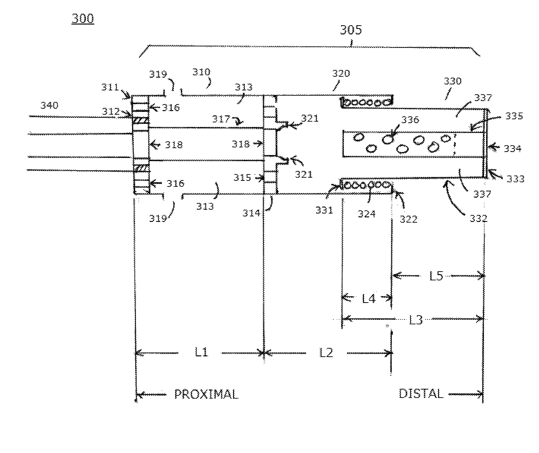
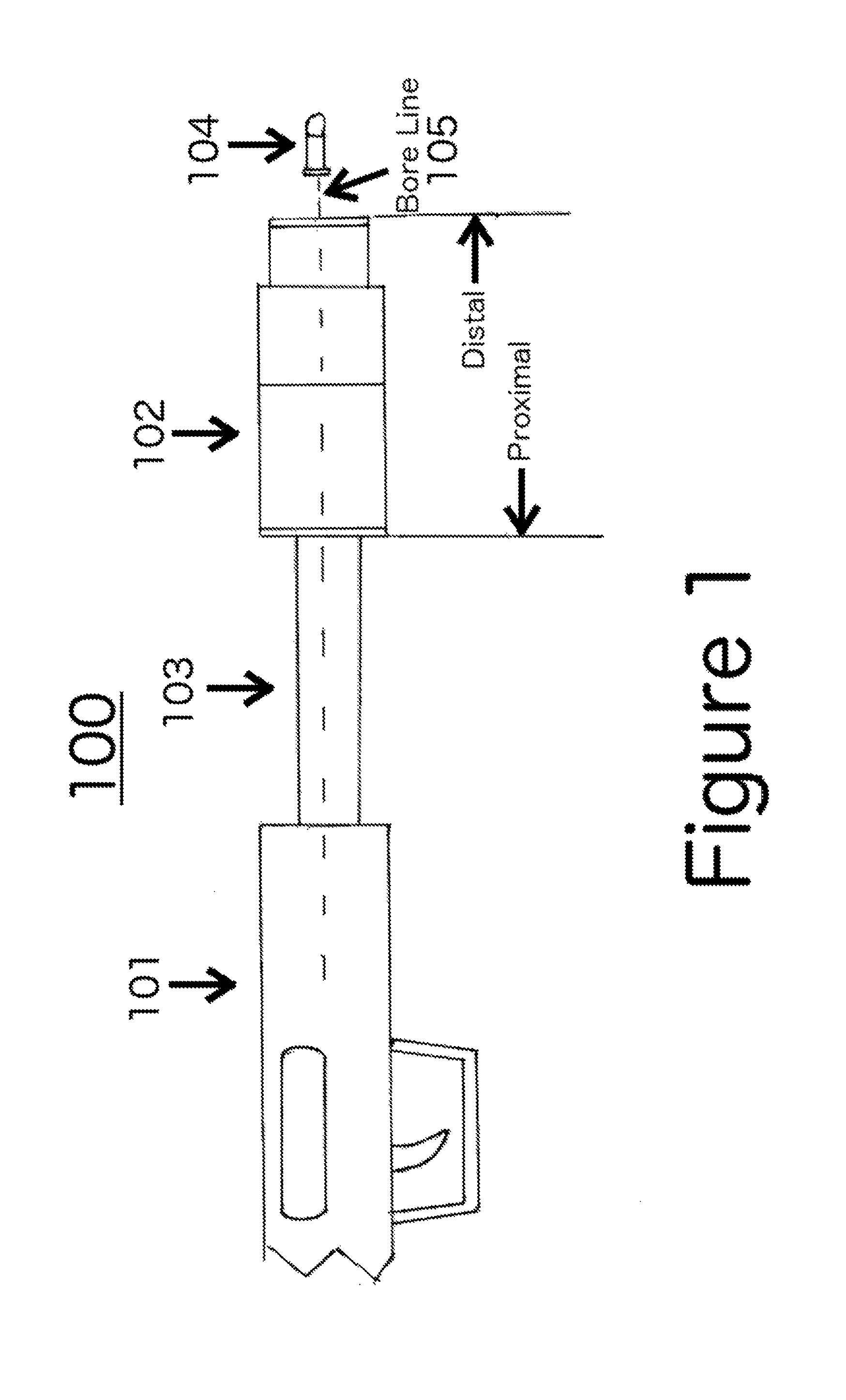
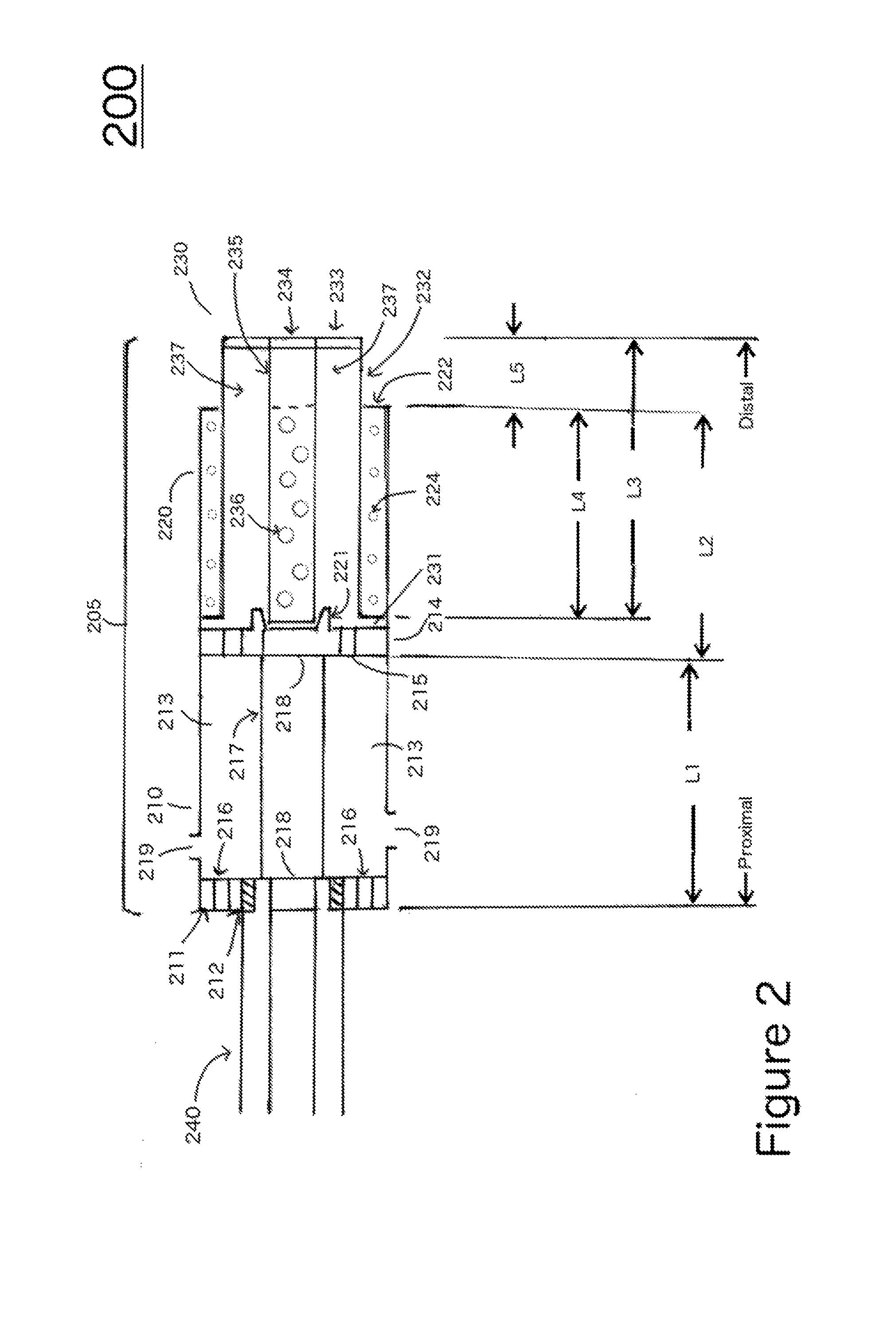
[0028]A silencer or noise suppressor for a firearm utilizing concepts of the invention is illustrated in FIG. 1. The silencer (102) can include a cylindrical body having a cylindrical bore proximally attached to the barrel (103) of a fi...


PUM


Abstract

A compact silencer device for a firearm comprising of multiple chambers which trap the gases from a projectile exiting the barrel of a gun to slow down the gases and reduce the temperature, sound, and flash associated with the projectile. In one embodiment, the first chamber which attaches to the barrel of the firearm comprises of sound baffling materials or gas porting baffles which vent gases from the second chamber passing rearward. The second chamber comprises of a chamber which can accommodate a retractable third chamber of the device, the second and third chamber of the device can have sound baffles to slow down the gases from the projectile.

Description

CROSS-REFERENCE TO RELATED APPLICATION[0001]This application is a divisional application of U.S. patent application Ser. No. 14 / 731,616 filed on Jun. 5, 2015 (which application claims the priority, under 35 U.S.C. .sctn.119, of U.S. Provisional Patent Application Ser. No. 62 / 008,260 filed on Jun. 5, 2014), the entire disclosures of which are hereby incorporated herein by reference in their entirety.BACKGROUND[0002]Firearm silencers are well known in the art of weaponry, and a variety of construction methods and materials have been proposed for minimizing the noise associated with expanding gases created or produced from the firing of a weapon. Sound energy is produced when the propellant in a cartridge (or shell) is ignited to force the bullet or shotgun projectile down the muzzle of a firearm. Silencers (also known as suppressors) for firearms operate on the principles of converting a portion of this sound energy into heat energy by diverting or trapping the pressurized gas in cham...

Claims


Application Information

Patent Timeline
Patent Type & Authority Patents(United States)
IPC IPC(8): F41A21/00F41A21/30
CPCF41A21/30
Inventor LAU, MICHAEL
Owner CGS TECH LLC
Why Eureka
Try Eureka