Support structures and deposition techniques for 3D printing

a support structure and 3d printing technology, applied in the field of additive manufacturing, can solve problems such as other defects within or on the 3d object, and achieve the effects of improving down-facing surfaces, easy separation, and easy separation

Active Publication Date: 2016-10-18
3D SYST INC
View PDF22 Cites 73 Cited by
  • Summary
  • Abstract
  • Description
  • Claims
  • Application Information

AI Technical Summary

Benefits of technology

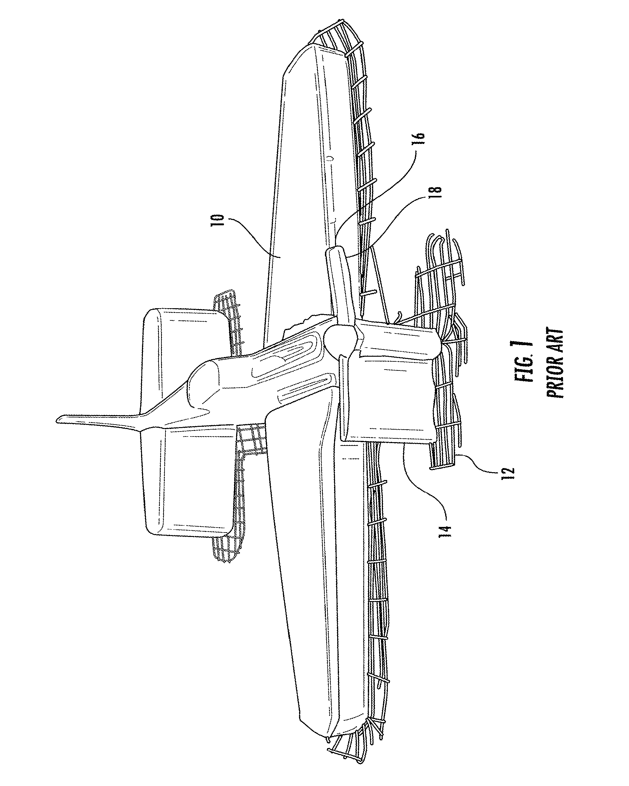
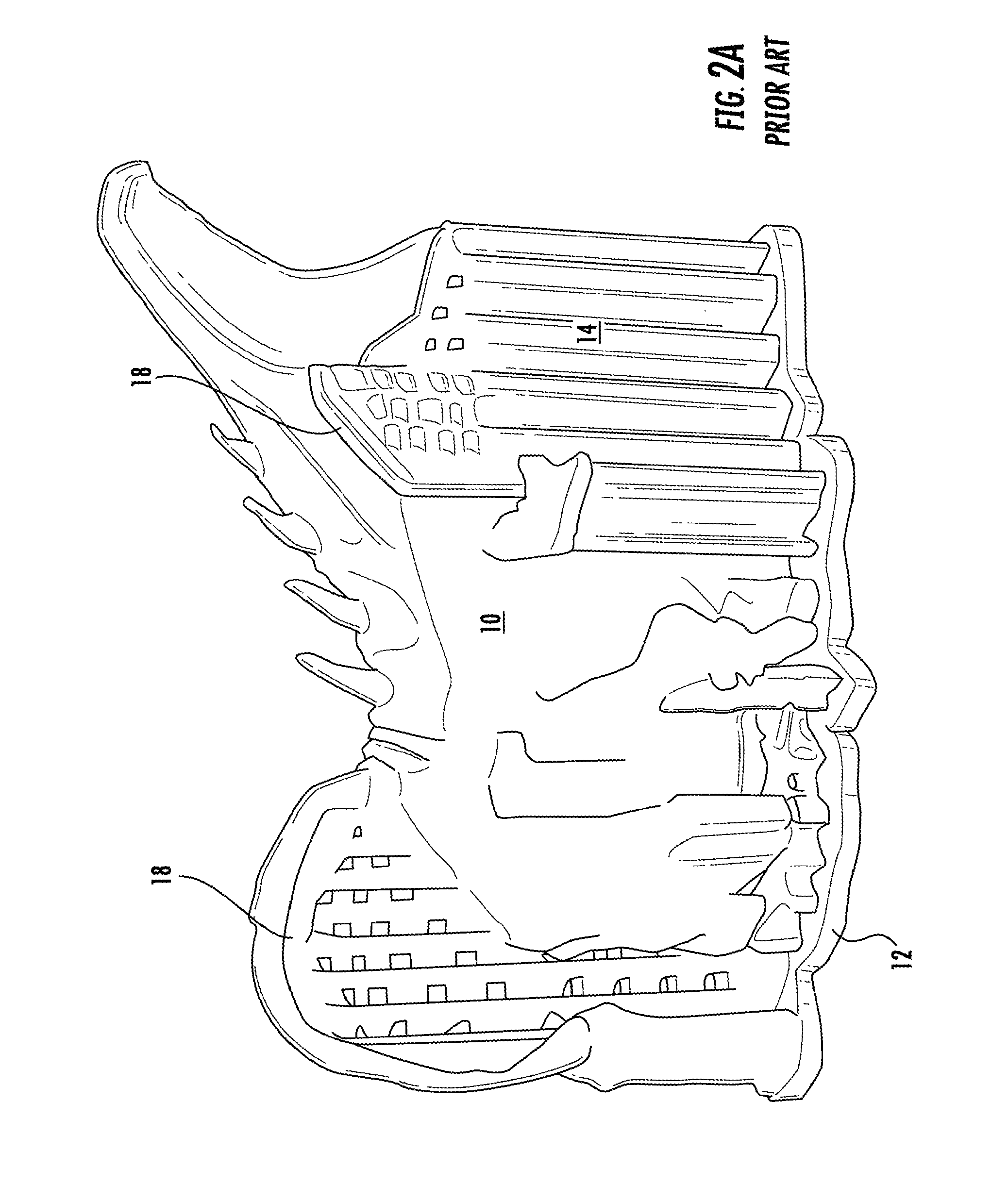
[0006]The various embodiments of the present invention address the above needs and achieve other advantages by providing novel support structures for extruded print materials and by providing an adhesive that provides satisfactory bonding of the extruded print material to the print pad during the print process yet enables the printed material to be easily separated from the print pad after the print process. These embodiments may be used individually or may be used together to allow printing of accurate 3D objects with improved down-facing surfaces that are easily separated from the support structures. These embodiments are particularly advantageous with 3D printing techniques that use the same print material to print the 3D object and the support structure; however, the embodiments may also be used with 3D printing techniques that use different materials to print the 3D object and the support structure.
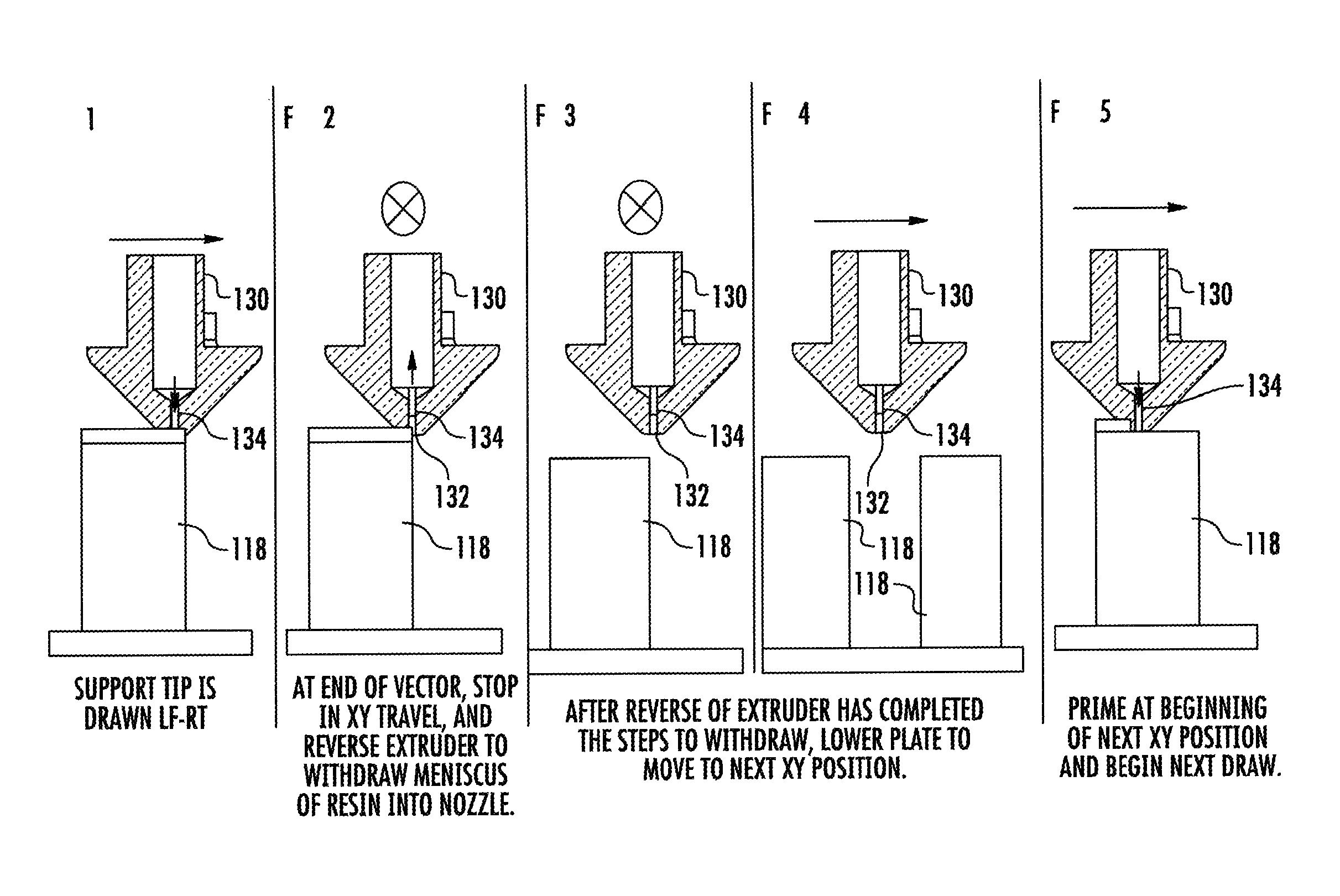
[0008]In some embodiments of the preset invention, the dispenser jumps between fine points by first dispensing material to print a first fine point. Once the fine point has been printed, the dispenser retracts the print material from the exit of the dispenser. The dispenser is then moved vertically relative to the first fine point, by moving the dispenser and / or the print pad, and then moved horizontally relative to the first fine point. By retracting, moving vertically, and then moving horizontally, the jump causes strings or blobs of excess material to be minimal or non-existent, thus enabling accurate printing of the fine points, which has not been possible by prior art techniques. In some embodiments, the dispenser is first moved in a direction that is not in the direction of the second fine point so that any string or blob of unintentional material does not accumulate with other strings or blobs that would cause the fine point to shift position. Certain embodiments move the dispenser in a first motion that is the direction opposite the direction of the second fine point to generally cause a string or blob to fall back upon the first fine point, which can be covered by subsequent layers of material. Still other embodiments move the dispenser in a first motion that is randomized or different for each layer so that the unintentionally dispensed material does not accumulate on one side to minimize the negative affect of such unintentionally dispensed material.
[0009]The methods of the present invention enable a single print material 3D printer to make a support structure that has accurate fine points that reliably support printed 3D objects and that are easily removed from the 3D object with minimal surface flaws to the surfaces of the 3D objects that contact the fine points. In some embodiments of the present invention, the fine points are very small, such as on the order of the size of the dispenser exit. In some embodiments the fine points have a horizontal cross-sectional size of about 1 mm in diameter or may define sizes such as 0.4 mm to 1.0 mm in the direction of movement of the dispenser and 1 to 2 mm in an orthogonal direction. Because strings and blobs are minimized, the distances of jumps can be reduced and can be on the order of 1 mm to 5 mm long, such as 2 mm long. Because of the improved accuracy of the fine points, the fine points can be relatively tall in a vertical direction, which enables the supports to be more easily removed, and consume less print material, than conventional support structure techniques.
[0012]The embodiments of the present invention provide for improved building of 3D objects by strengthening the support structure provided for the 3D object during printing, and by enabling the support structure to be more easily removed from the 3D object after printing.

Problems solved by technology

Such unintentionally dispensed material can impair the accuracy of the fine points and cause them to inadequately support the 3D object, resulting in flaws on the down-facing surfaces of the 3D object or lead to other defects within or on the 3D object.

Method used


Image

  • Support structures and deposition techniques for 3D printing
  • Support structures and deposition techniques for 3D printing
  • Support structures and deposition techniques for 3D printing

Examples


Embodiment Construction

[0026]The present invention now will be described more fully hereinafter with reference to the accompanying drawings, in which some, but not all embodiments of the invention are shown. Indeed, the invention may be embodied in many different forms and should not be construed as limited to the embodiments set forth herein; rather, these embodiments are provided so that this disclosure will satisfy applicable legal requirements. Although apparatus and methods for supporting 3D objects during printing are described and shown in the accompanying drawings with regard to specific types of 3D printing techniques, it is envisioned that the functionality of the various apparatus and methods may be applied to any now known or hereafter devised 3D printing technique. Like numbers refer to like elements throughout.

[0027]With reference to FIGS. 4 to 14, support structures and print techniques for use with 3D printing techniques in accordance with various embodiments of the present invention are i...


PUM

PropertyMeasurementUnit
jump distanceaaaaaaaaaa
diameteraaaaaaaaaa

Abstract

There is provided a support structure for use with 3D printing of objects from computer-aided designs. The support structures include fine points that contact the down-facing surfaces of the 3D object being printed in order to adequately support the 3D object while also being adapted for easy removal after the 3D print process is complete. The fine points are possible by controlling the operation of the dispenser to provide a precise amount of material in a precise location. The dispenser jumps from a first fine point to a second fine point by retracting the print material after the first fine point is printed and then moving the dispenser vertically relative to the first fine point before the dispenser is moved horizontally to the second fine point.

Description

FIELD OF THE INVENTION[0001]The present invention is related to additive manufacturing, and more particularly, to methods and compositions for supporting and printing objects during the printing of three dimensional (3D) objects.BACKGROUND OF THE INVENTION[0002]Additive and subtractive manufacturing technologies enable computer designs, such as CAD files, to be made into 3D objects. 3D printing, also known as additive manufacturing, typically comprises depositing, curing, fusing, or otherwise forming a material into sequential cross-sectional layers of the 3D object. For example, fused deposition modeling techniques, which are generally disclosed in U.S. Pat. No. 4,749,347 and U.S. Pat. No. 5,121,329, among others, which are incorporated by reference herein in their entirety, include melting a filament of build material and extruding the print material out of a dispenser that is moved in the x-, y-, and z-axes relative to a print pad. The print material is generally deposited in lay...

Claims


Application Information

Patent Timeline
Patent Type & Authority Patents(United States)
IPC IPC(8): B29C67/00C09J133/08C09J179/00B29C37/00C09J129/04C08G73/02C09J179/02C09J177/00C09J129/10B29K29/00B29K33/04
CPCB29C37/0003B29C67/0055B29C67/0085B29C67/0092C08G73/0233C09J129/04C09J129/10C09J133/08C09J177/00C09J179/00C09J179/02C08L79/02C08L29/04B29K2029/04B29K2033/04B33Y10/00B29C64/40B29C64/118B29C64/245B29C64/106B29C64/124
Inventor JOHNSON, MARTIN ALANMANNERS, CHRIS ROBERTSEDWARDS, ANDREW
Owner 3D SYST INC
Why Eureka
Try Eureka