
Water separator and system

a technology of water separator and water tank, which is applied in the field of water separator and system, can solve the problems of increasing the weight and cost of the system, occupying a considerable amount of space for the external moisture separator b>12/b>, and hot compressed air, so as to reduce the horizontal velocity of the horizontal air flow and the effect of greater cross-sectional area

Active Publication Date: 2016-10-25
API HEAT TRANSFER
View PDF33 Cites 0 Cited by
  • Summary
  • Abstract
  • Description
  • Claims
  • Application Information

AI Technical Summary

Benefits of technology

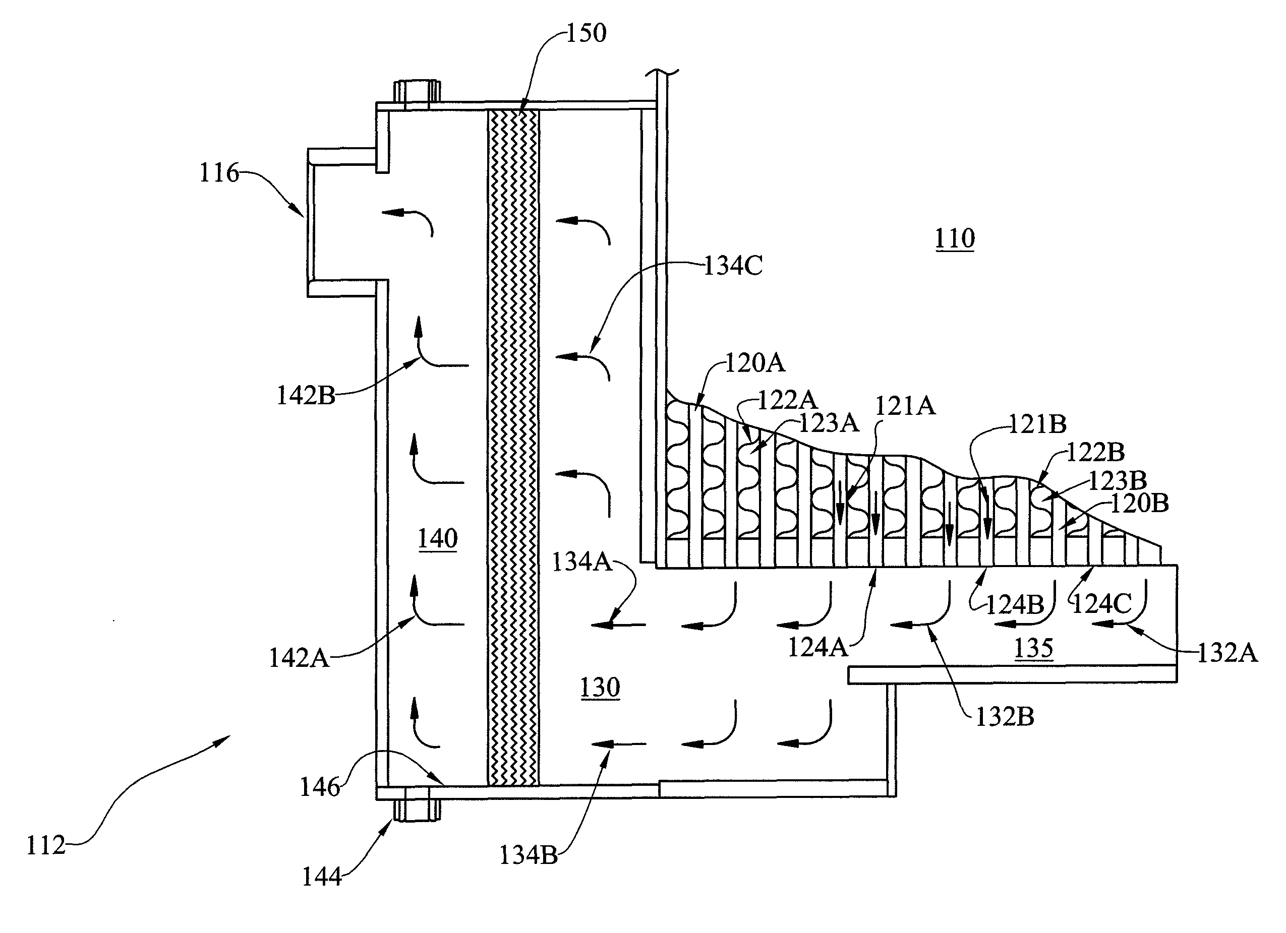
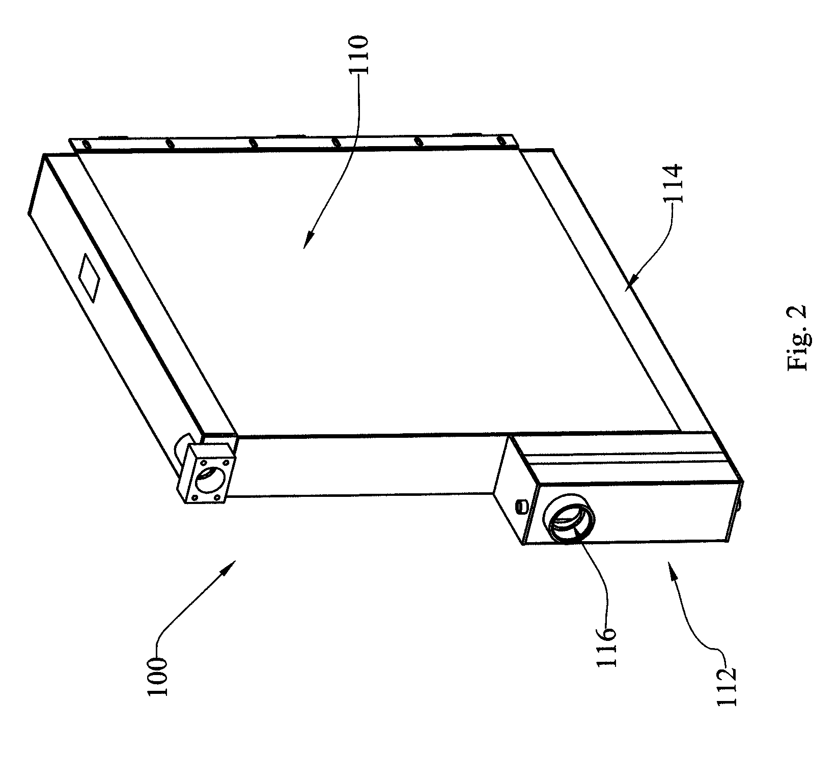
[0007]Another aspect of the invention provides a cooling and water removal system having a cooling unit with multiple compartments: an aftercooler disposed within a first compartment; a horizontal air flow path disposed within a second compartment; a demister core disposed within a third compartment; and an exit compartment downstream from the demister core. In another aspect, an additional compartment, a flow reduction compartment, is included directly adjacent to the second compartment and in fluid communication with the horizontal air flow path, wherein the flow reduction compartment has a greater cross-sectional area than the second compartment, to reduce the horizontal velocity of the horizontal air flow.

Problems solved by technology

The temperature increase can be significant enough to make the compressed air quite hot and unusable for many applications.
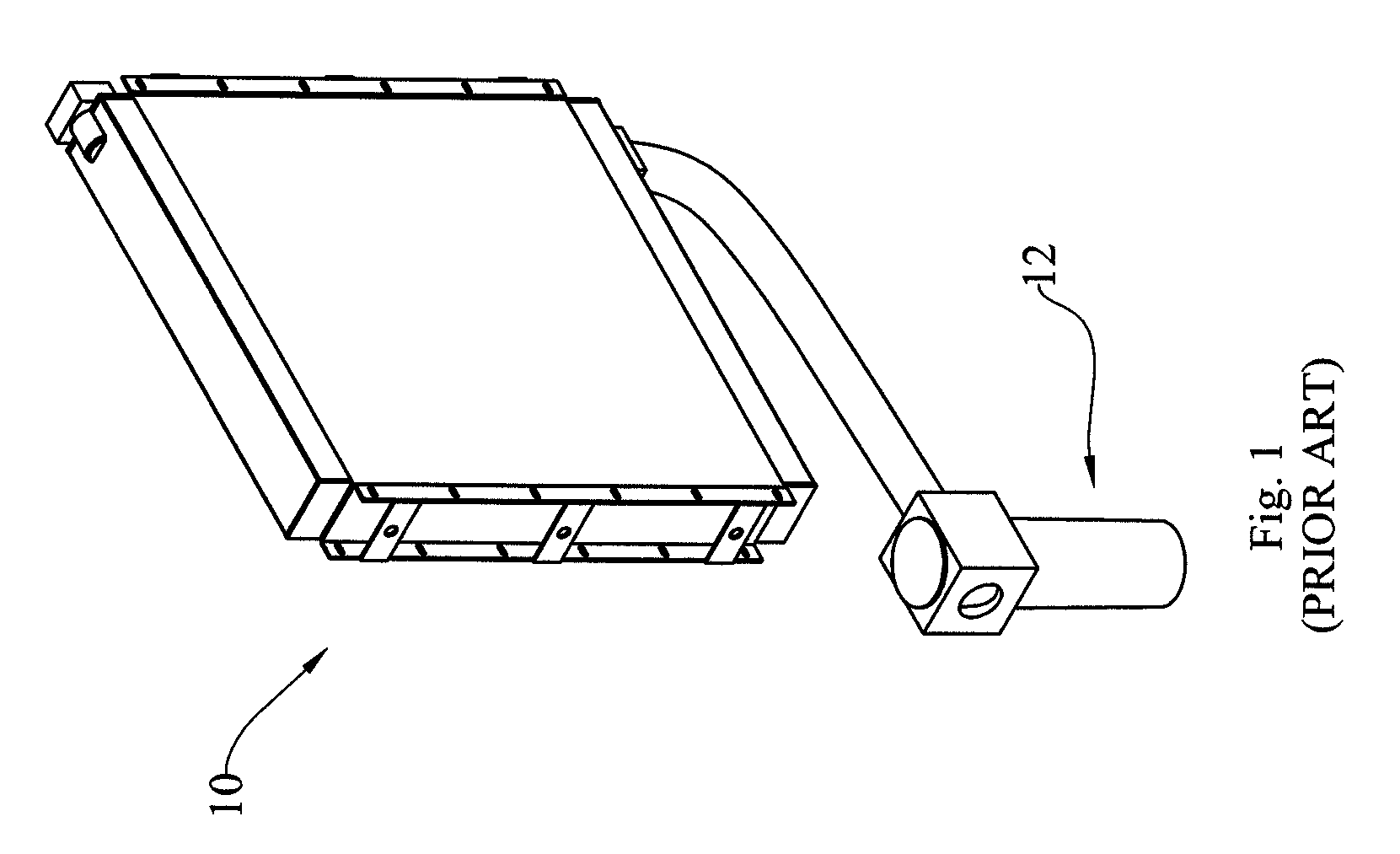
An external moisture separator 12 may take up a considerable amount of space and add weight and cost to a system.

Method used


Image

  • Water separator and system
  • Water separator and system
  • Water separator and system

Examples


Embodiment Construction

[0018]At the outset, it should be clearly understood that like reference numerals are intended to identify the same structural elements, portions or surfaces consistently throughout the several drawing figures, as such elements, portions or surfaces may be further described or explained by the entire written specification, of which this description is an integral part. Unless otherwise indicated, the drawings are intended to be read (e.g., cross-hatching, arrangement of parts, proportion, degree, etc.) together with the specification, and are to be considered a portion of the entire written description of this invention. As used in the following description, the terms “horizontal”, “vertical”, “left”, “right”, “up” and “down”, as well as adjectival and adverbial derivatives thereof (e.g., “horizontally”, “rightwardly”, “upwardly”, etc.), simply refer to the orientation of the illustrated structure as the particular drawing figure faces the reader. Similarly, the terms “inwardly” and...


PUM


Abstract

A water separator and system includes a compressed air aftercooler and water / moisture separator with a demister core comprising a plurality of offset fins. In one embodiment, the compressed air aftercooler comprises a compressed air core having an aftercooler inlet, an aftercooler outlet at the bottom of the compressed air core, and one or more heat transfer passages. In one aspect, the system comprises a moisture separator substantially integral to the aftercooler. In another aspect, the system includes a first generally horizontal region beneath and adjacent to the aftercooler outlet; and an expansion zone adjacent to and in fluid communication with the first region, the expansion zone being configured to reduce the horizontal velocity of compressed air passing therethrough. In another aspect, the demister core is in fluid communication with the expansion zone. In certain aspects, the demister core comprises a plurality of offset fins creating an undulating / uneven flow and / or creating air flow direction change. Another aspect includes an exit zone downstream from the demister core, wherein the exit zone has a compressed air outlet and a condensate drain.

Description

RELATED APPLICATIONS[0001]This is the U.S. National Stage application of International Application No. PCT / US2009 / 066975, filed Dec. 7, 2009, which claims priority to U.S. Provisional Patent Application No. 61 / 176,071, filed May 6, 2009, both incorporated herein by reference.BACKGROUND OF THE INVENTION[0002]When humid ambient air is compressed in an air compressor, thermodynamic processes occur that raise the air temperature and the dew point temperature. The dew point temperature as used herein is the temperature at which the relative humidity becomes 100% saturated and water vapor in the compressed air begins to condense into liquid.[0003]The temperature increase can be significant enough to make the compressed air quite hot and unusable for many applications. To reduce the temperature of the compressed air to a usable range, certain air compressor systems use water or air cooled aftercoolers—named thus because they are located downstream from the compressor. Aftercoolers cool the...

Claims


Application Information

Patent Timeline
Patent Type & Authority Patents(United States)
IPC IPC(8): F25D17/06F25D21/14F24F13/22F24F3/14
CPCF24F13/222F24F2003/1446
Inventor GALUS, TIMOTHY JSTROMECKI, JOHNBEECHLER, TIMOTHY
Owner API HEAT TRANSFER
Learn More