Method and system for molten slag granulation and sensible heat recovery

A sensible heat recovery and slag technology, applied in the direction of process efficiency improvement, etc., can solve the problems of high investment and operating costs, large water consumption, and reduce the effect of granulation, so as to reduce the volume and floor area, and achieve the level of The effect of short flight distance and reduced energy loss

Active Publication Date: 2014-04-02
TSINGHUA UNIV
View PDF6 Cites 0 Cited by
  • Summary
  • Abstract
  • Description
  • Claims
  • Application Information

AI Technical Summary

Problems solved by technology

[0004] At present, liquid blast furnace slag is mainly quenched by water quenching method. The blast furnace slag after water quenching can be used to make building materials such as cement. The problems of water quenching method are: (1) It consumes a lot of water. The pressure of the water jet is generally between 0.2MPa and 0.8MPa. The jet velocity is low and the impact ability is weak. Therefore, the flow rate must be increased to meet the needs of slag flow breaking. At the same time, a large amount of water is required to cool the slag. Therefore, the water consumption for processing one ton of slag can be as high as 5-10 tons, and about 1 ton of new water needs to be evaporated to process each ton of slag; (2) A large amount of H is produced. 2 S and SO x Cause secondary pollution; (3) The sensible heat of blast furnace slag has not been recovered; (4) The water content of water-quenched slag is high, and it still needs to consume energy for drying when used as cement raw material; (5) The fine particles contained in circulating water are harmful to The wear and blockage of pumps, valves and other components is very serious, and the system maintenance workload is very heavy, which increases maintenance costs
The wind quenching method is to use a high-power granulation fan to generate a high-speed airflow to blow away the liquid blast furnace slag and solidify it to complete the granulation. Its main disadvantages are large power consumption, large and complex equipment, large floor area, high investment and operating costs, When the flow rate of liquid blast furnace slag changes, the wind speed and air volume are not easy to coordinate, and a large amount of cold air enters the system, which also reduces the quality of waste heat
The centrifugal method relies on the centrifugal force generated by the high-speed rotation of the turntable or cup to break the liquid blast furnace slag. Although it does not require high-energy-consuming equipment such as a granulation fan, the particle size distribution of the slag after granulation is relatively uniform, but the high-speed rotation at high temperature The reliability of the granulation device is poor, and the granulation effect is more sensitive to the temperature and flow changes of the liquid blast furnace slag. The effect of adjusting the speed alone is not ideal, so there are certain difficulties in large-scale, and the high-speed scattering of molten slag is also difficult. It is not conducive to the compact design of the equipment. The high-temperature slag hits a certain part of the equipment at high speed, and it is easy to cause local overheating of the equipment and damage the equipment.
[0009] In addition, regardless of the wind quenching method or the centrifugal method, a large amount of slag wool is likely to be generated during the crushing process of liquid blast furnace slag, which reduces the effect of granulation, and slag wool is easy to entangle and accumulate inside the equipment, affecting the stability of equipment operation , and may also cause fibrous dust pollution

Method used


Image

  • Method and system for molten slag granulation and sensible heat recovery
  • Method and system for molten slag granulation and sensible heat recovery
  • Method and system for molten slag granulation and sensible heat recovery

Examples


Embodiment Construction

[0038] The method for slag granulation and sensible heat recovery provided by the present invention and the slag granulation and sensible heat recovery system using the method will be described in detail below with reference to the accompanying drawings.

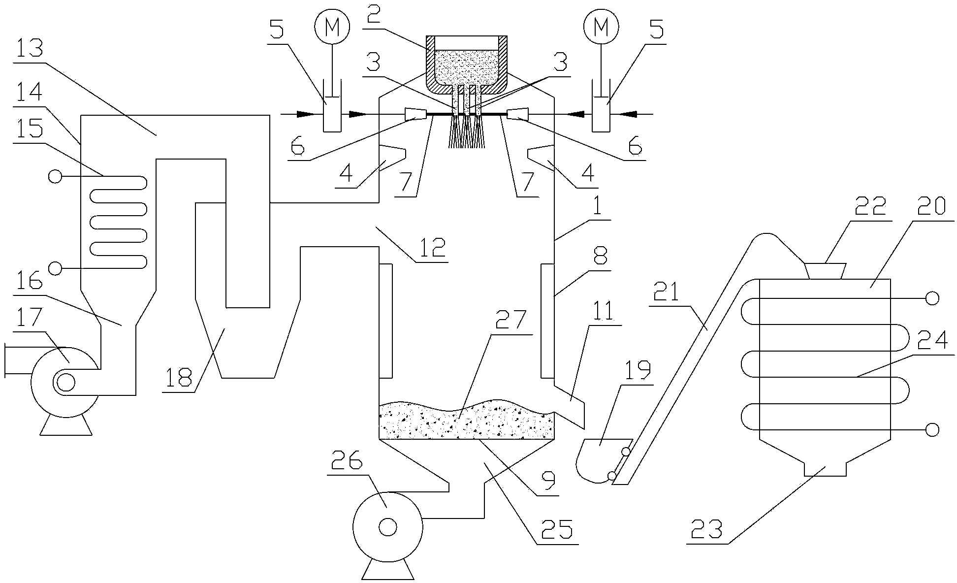
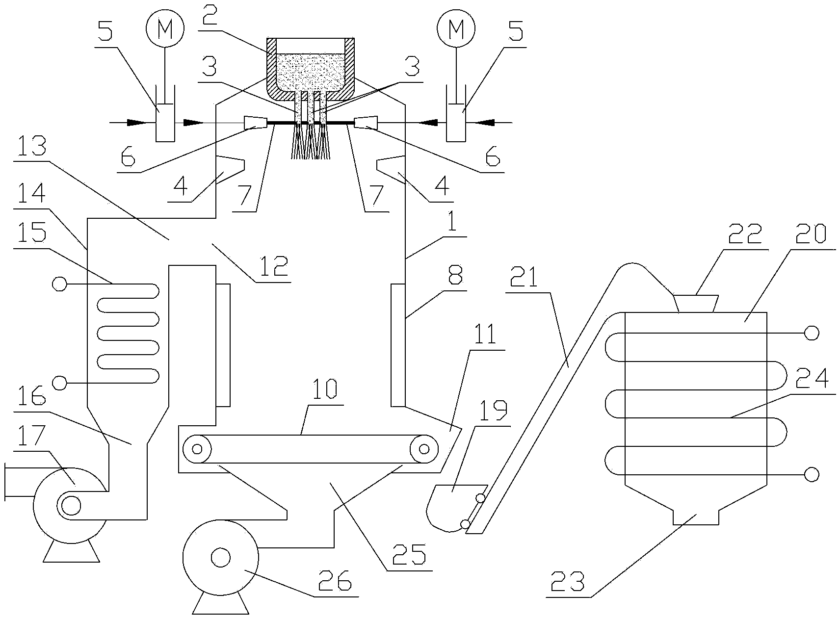
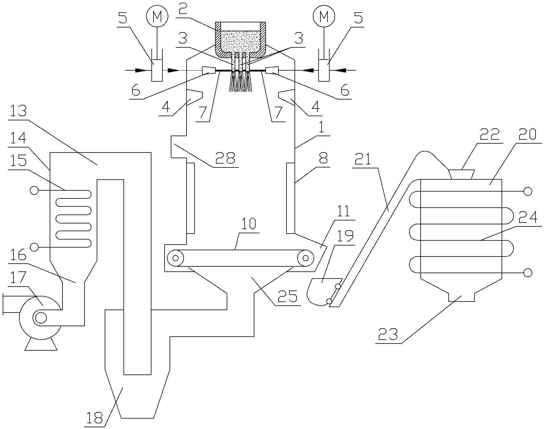
[0039] A method for slag granulation and sensible heat recovery provided by the invention comprises the following steps:

[0040] 1) Let the slag flow into the shell from the leakage bag to form multiple columnar slag flows, and the multiple columnar slag flows are arranged in at least one row, and the number of strands of each columnar slag flow is at least two;

[0041] 2) Install at least one nozzle in the shell with water cooling wall, pressurize the water to 1MPa ~ 400MPa with a high-pressure pump, and spray it from at least one nozzle to form a columnar high-speed water jet with a flow rate of at least 45m / s at the outlet of the nozzle;

[0042] 3) The high-speed water jet impacts the multiple columnar slag flows on th...


PUM


Abstract

The invention discloses a method and a system for molten slag granulation and sensible heat recovery, and belongs to the technical field of industrial waste residue treatment and utilization. The method comprises the following steps of: pressurizing water, and injecting water from a nozzle to form a columnar high-speed water jet flow; impacting multiple strands of columnar molten slag flows on the same row in sequence; breaking the molten slag; in the falling process, cooing the broken molten slag by a water cooling wall; recovering parts of sensible heat; then, falling into the bed layer of a fluidized bed or a travelling grate to be cooled by air entering from outside, completely solidifying the molten slag to finish granulation and obtain hot air; sending hot air obtained on the fluidized bed or the travelling grate into a waste heat boiler to recover heat; and sending solidified molten slag particles output out of the fluidized bed or the travelling grate into a moving bed for further recovering the sensible heat. The molten slag can be broken by the high-speed water flow, the breaking and flying effect of the method is good, a slag wool generation amount is small, slag wool is easy to process because the slag wool contains water, the operation energy consumption and the water consumption of the slag wool are low, and therefore the sensible heat recovery of the molten slag can be favorably carried out.

Description

technical field [0001] The invention relates to a method and system for slag granulation and sensible heat recovery, belonging to the technical field of industrial waste slag treatment and utilization. Background technique [0002] Slag is a high-temperature, molten industrial waste produced in the process of combustion, metallurgy or chemical production, such as liquid blast furnace slag, steel slag, copper slag, phosphorus slag, etc., which contains rich sensible heat resources. [0003] Liquid blast furnace slag is a typical slag. The annual production of blast furnace slag in my country is hundreds of millions of tons, which is a huge amount. Its treatment technology is representative in the slag treatment technology. Blast furnace slag is a silicate material with good properties, which can be used as a raw material for the production of building materials and fertilizers. Among them, blast furnace slag after quenching treatment has no time to form crystals in the proce...

Claims


Application Information

Patent Timeline
Patent Type & Authority Patents(China)
IPC IPC(8): C21B3/08C04B5/00C04B5/02
CPCC21B2400/024C21B2400/062C21B2400/076C21B2400/08Y02P10/20
Inventor 张衍国杜滨王友才李清海蒙爱红
Owner TSINGHUA UNIV
Why Eureka
Try Eureka