Device and method for diagnosing evaporated fuel processing device

a technology of processing device and evaporated fuel, which is applied in the direction of machines/engines, fluid-tightness measurement, instruments, etc., can solve the problem of low frequency of situations where diagnosis is actually possible, and achieve the effect of reducing the amount of evaporated fuel to be processed and reducing the amount of evaporated fuel

Active Publication Date: 2016-10-25
NISSAN MOTOR CO LTD
View PDF36 Cites 8 Cited by
  • Summary
  • Abstract
  • Description
  • Claims
  • Application Information

AI Technical Summary

Benefits of technology

[0009]Namely, the diagnostic apparatus according to the present invention causes the pump to pressurize the system including the fuel tank and the canister, and determines whether leakage is present, based on pressure change thereafter. This prevents a fuel component from being sucked from the canister to the outside. Accordingly, the diagnostic apparatus can perform the diagnosis even in a situation where a relatively large amount of evaporated fuel is adsorbed in the canister. Moreover, since the internal pressure of the system is raised during the diagnosis, evaporation of fuel in the fuel tank is suppressed in contrast to the conventional technology. Furthermore, since the inside of the fuel tank is maintained in pressurized state by the pressurization during the diagnosis, also after the diagnosis, the occurrence of evaporated fuel is suppressed so that the amount of evaporated fuel to be processed is reduced.
[0010]Accordingly, the present invention makes it possible to perform the diagnosis even when a relatively large amount of evaporated fuel is adsorbed in the canister, and suppress the occurrence of evaporated fuel in the fuel tank while the vehicle is stationary after the diagnosis, and thereby reduce the amount of evaporated fuel to be processed by the evaporated fuel processing apparatus.

Problems solved by technology

However, in the conventional diagnostic apparatus, air is sucked by the negative pressure pump from the system via the canister, so that when a large amount of evaporated fuel is adsorbed in the canister, a fuel component may flow from the canister to the outside via the negative pressure pump.
Accordingly, this apparatus has a defect that the frequency of situations where the diagnosis is actually possible is low.

Method used


Image

  • Device and method for diagnosing evaporated fuel processing device
  • Device and method for diagnosing evaporated fuel processing device
  • Device and method for diagnosing evaporated fuel processing device

Examples


Embodiment Construction

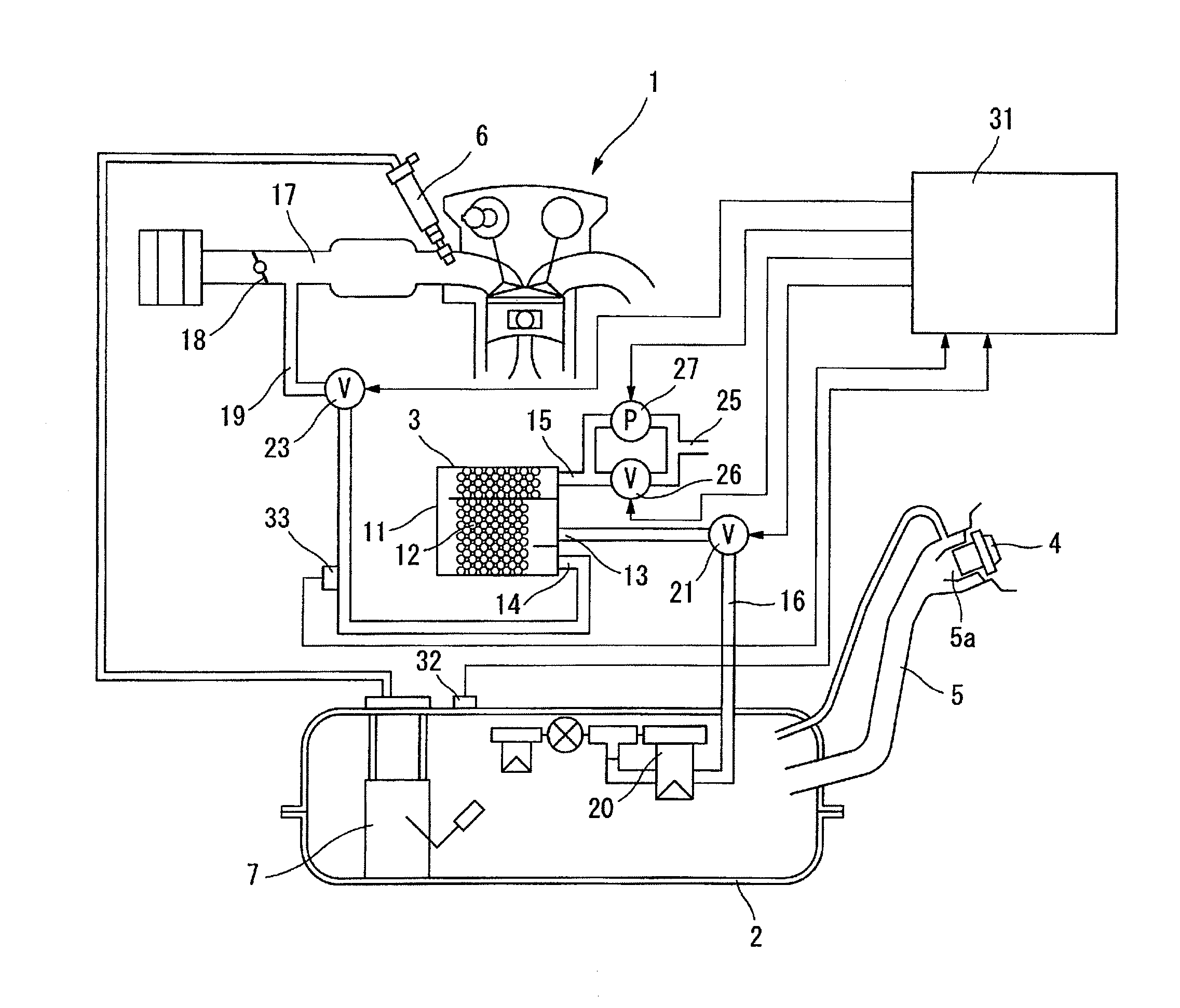
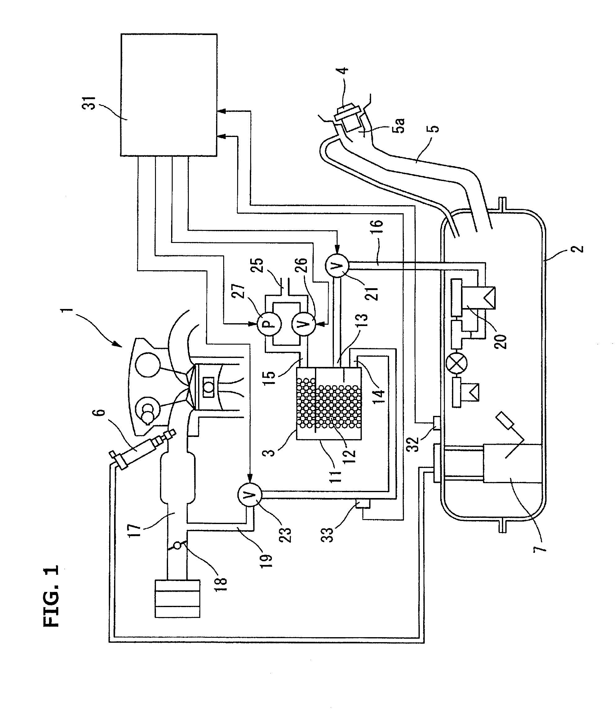
[0016]FIG. 1 is a configuration diagram showing an embodiment of an evaporated fuel processing apparatus provided with a diagnostic apparatus according to the present invention. An internal combustion engine 1 is mounted on a vehicle not shown which is provided with a fuel tank 2 of a hermetic type, and is provided with an evaporated fuel processing apparatus which employs a canister 3 for processing evaporated fuel occurring in fuel tank 2 during fuel filling. The fuel tank 2 includes a filler pipe part 5 having a filler opening 5a at its tip, wherein a filler cap 4 is attached detachably to filler opening 5a. A fuel pump unit 7 is mounted in fuel tank 2 for supplying fuel to a fuel injection device 6 of internal combustion engine 1.

[0017]The canister 3 includes an U-shaped flow path formed by a case 11 made of synthetic resin, and is filled therein with an adsorbent 12 made of activated carbon or the like. One end portion of the U-shaped flow path in the flow direction is provided...


PUM


Abstract

An evaporated fuel processing apparatus includes a valve between a canister and a fuel tank, and adsorbs evaporated fuel by the canister during fuel filling, and introduces into an intake air line of an internal combustion engine and processes the evaporated fuel while the internal combustion engine is operating. A diagnostic apparatus includes: a pump for pressurizing a system including the fuel tank and the canister; and a pressure sensor for sensing an internal pressure of the system. The diagnostic apparatus diagnoses whether or not leakage is present, based on a change in the internal pressure of the system from a pressurized state, wherein the pressurized state is a state pressurized to a predetermined pressure for diagnosis that is higher than a tank pressure at start of diagnosis; and maintains the fuel tank in the pressurized state by closing the valve after termination of the diagnosis.

Description

TECHNICAL FIELD[0001]The present invention relates to an evaporated fuel processing apparatus that employs a canister to process evaporated fuel occurring in a fuel tank during fuel filling, and relates particularly to a diagnostic apparatus and a diagnostic method for diagnosing whether or not the evaporated fuel processing apparatus is leaking.BACKGROUND ART[0002]An evaporated fuel processing apparatus has been widely used, which is configured to: temporarily adsorb evaporated fuel in a canister for preventing the evaporated fuel from flowing to the outside, wherein the evaporated fuel occurs in a fuel tank of a vehicle, and the canister is made of an adsorbent such as activated carbon; and thereafter purge a fuel component from the canister by introduction of fresh air and introduce the fuel component into an intake air line of an internal combustion engine while the internal combustion engine is operating.[0003]A patent document 1 discloses an evaporated fuel processing apparatu...

Claims


Application Information

Patent Timeline
Patent Type & Authority Patents(United States)
IPC IPC(8): G01M3/02G01M3/04F02M25/08G01M3/28G01M3/32
CPCG01M3/04F02M25/0818G01M3/025G01M3/2876G01M3/3236
Inventor TAKAKURA, SHINSUKEOTSU, ISAO
Owner NISSAN MOTOR CO LTD
Why Eureka
Try Eureka