High resolution light microscope

a light microscope, high-resolution technology, applied in the direction of instruments, optical elements, fluorescence/phosphorescence, etc., can solve the problems of time-consuming deflection of excitation light over the sample, high device precision of optical path alignment, time-consuming sequential irradiation and locating of individual molecules, etc., to achieve high resolution and reduce configuration effort

Active Publication Date: 2016-10-25
TECH UNIV BRAUNSCHWEIG
View PDF5 Cites 3 Cited by
  • Summary
  • Abstract
  • Description
  • Claims
  • Application Information

AI Technical Summary

Benefits of technology

[0006]The object of the present invention is to provide an alternative apparatus and an alternative process for the optical detection of fluorescent molecules in a sample with high resolution, preferably in the provision of an apparatus which allows a reduced configuration effort, in particular for focusing, and which allows for a process that can be performed with any molecule that is fluorescent when irradiated with an excitation wavelength, and which preferably spatially resolves a multitude of molecules. Furthermore, the process shall not be limited e.g. to fluorescent molecules that are switchable by a switching wavelength.GENERAL DESCRIPTION OF THE INVENTION
[0017]In addition to the first detector described above, the apparatus optionally has at least one second detector onto which the light emitted by the probe is directed e.g. by means of a partially transparent mirror, and which is preferably coupled with a signal analysis device that is set up to exclusively collect or isolate those detected signals that are detected with a constant phase shift to the modulation signal which is used to control the polarization modulator, or to the modulation signal used by the polarization modulator to modulate polarization of the excitation light. A partially transparent mirror generally is e.g. a polarization beam splitter. In the process, such a detector collects different components of the light emitted by the fluorescent molecules, preferably the polarization which is random according to the different orientation of the transition dipole moment vectors of the fluorescent molecules and Which therefore results in a scattered detection of fluorescent molecules. In embodiments having a first and at least one second detector that are each coupled to a signal analysis device, from the different phase shift, modulation amplitude and the medium intensity of the light emitted by the fluorescent molecules which the two signal analysis devices collect and isolate, a higher spatial resolution of individual molecules is achieved.
[0022]Optionally the light source can be configured to generate excitation light of one or of at least two light frequencies the sum of which is equal to the frequency of the excitation light that is specific for the fluorescent molecule, in particular when using the apparatus as a microscope for the so-called two photon excitation or multiple photon excitation. In embodiments in which the light source is configured to generate the excitation light with light frequencies the sum of which is equal to the frequency of the excitation light that is specific for the fluorescent molecules, multiple photon excitation is implemented, which has the benefit of a smaller angle range in which the fluorescent molecules are suitably oriented so that a higher resolution results.
[0025]Special preference is on an apparatus where the first and the second light source are linearly polarized, with the polarization of the de-excitation light beam having an angle of >0 to <180°, preferably 60° to 120°, in particular 90° to the polarization of the excitation light beam, e.g. by means of a polarization modulator located in their beam path. In this embodiment, only those fluorescent molecules are not de-excited whose transition dipole moment vectors exactly match the polarization of the excitation light beam so that the angle range of the suitably oriented fluorescent molecules is drastically reduced so that as a consequence individual molecules have a much better resolution and can be better distinguished.

Problems solved by technology

This process is disadvantageous in that the device requires an extremely high precision of optical path alignment for the excitation wavelength and for the de-excitation wavelength and a time-consuming deflection of excitation light over the sample, e.g. by means of a scanner.
This process is disadvantageous in that it is limited to those fluorescent molecules which are to be brought to an excitable state using a switching wavelength radiation, with time duration suitable for the analysis, and that the sequential irradiation and locating of the individual molecules is time consuming.

Method used


Image

  • High resolution light microscope
  • High resolution light microscope
  • High resolution light microscope

Examples


Embodiment Construction

[0037]The invention is now described in more details with reference to the figures that schematically show in

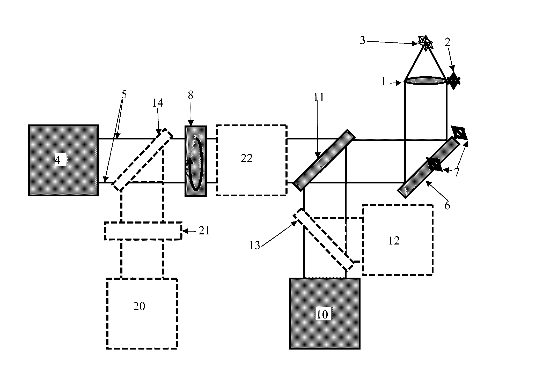
[0038]FIG. 1 an embodiment,

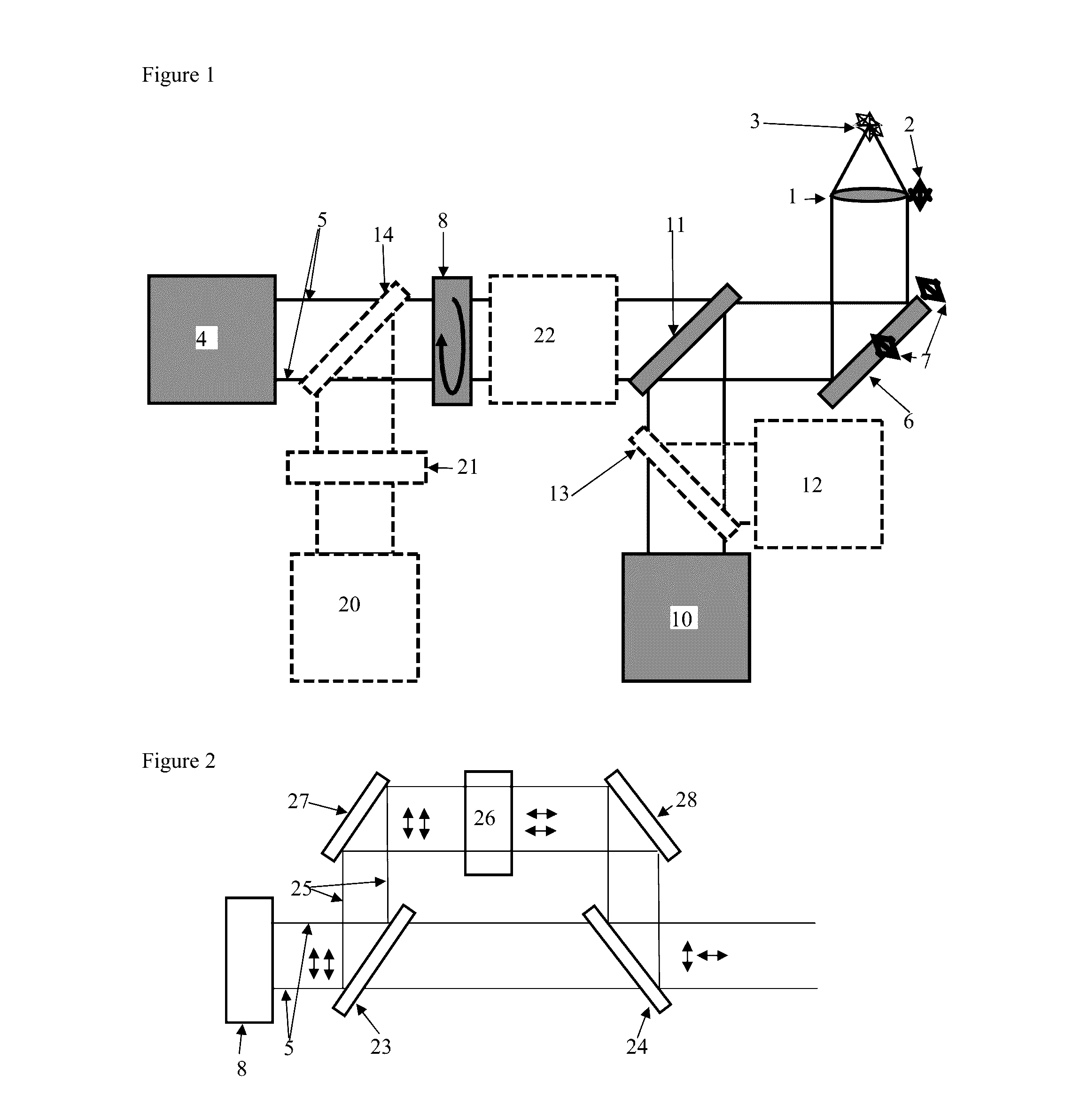
[0039]FIG. 2 a section of a preferred embodiment,

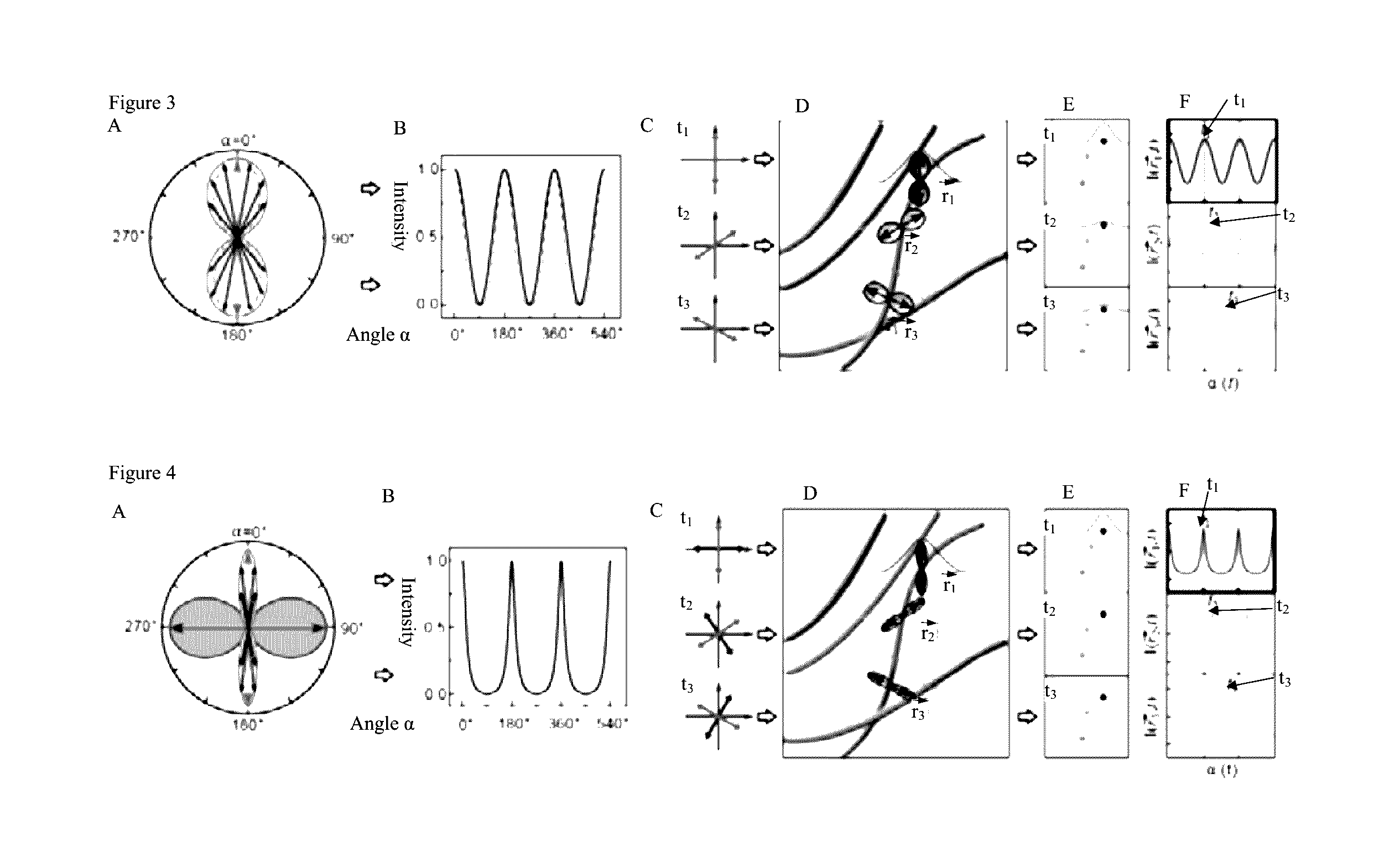
[0040]FIG. 3, A to F, the modulation and demodulation in an embodiment of the process with excitation light only, and

[0041]FIG. 4, A to F, the modulation and demodulation in an embodiment of the process with excitation light and de-excitation light.

[0042]Using the focusing device 2, objective 1 can be focused on sample 3 which contains fluorescent molecules. An excitation light source 4 produces excitation light 5 the beam path of which is directed into the objective 1, shown here by means of a mirror 6 that is deflecting and controlled by means of the control device 7, e.g. for controlled guidance of excitation light 5 over sample 3.

[0043]The polarization modulator 8 is configured to modulate the polarization of the excitation light 5, which preferably is a linear polarization direction, with at leas...


PUM

PropertyMeasurementUnit
angleaaaaaaaaaa
angleaaaaaaaaaa
angleaaaaaaaaaa

Abstract

The present invention relates to an apparatus for the optical analysis of a sample, also referred to as microscope, which is configured for an optical analysis process having high resolution for the detection of fluorescent molecules. The apparatus and the process applied when using the apparatus are configured for excitation light generated by an excitation light source to be directed onto a sample and the light emitted by the probe is detected. The apparatus and the process are characterized in that the excitation light is synchronized with the detection. The apparatus is characterized in that it has a polarization device which is configured to modulate the polarization of the excitation light with a modulation signal, wherein the modulation signal has or consists of at least one frequency, in particular a pre-determined frequency or several pre-determined superimposed frequencies, or the modulation signal consists of a sequence of signals that has no repetition.

Description

[0001]The present invention refers to an apparatus for the optical analysis of a sample, also referred to as microscope, which is configured for a high resolution optical analysis process for the detection of fluorescent molecules. The apparatus and the process applied by using the apparatus are arranged such that the excitation light generated by the excitation light source is focused on a sample and that the light emitted by the sample is detected. The apparatus and the process are characterized by the fact that the excitation light is synchronized with the detection. The excitation light source may consist of a laser device.STATE OF THE ART[0002]US 2001 / 045523 describes the stimulated emission depletion microscopy (STED) which involves a sample being irradiated and sampled via a microscope objective by two parallel light paths, while light emitted by the sample exits through the same optical path and is detected. One of the light beams is coupled into the optical path by means of...

Claims


Application Information

Patent Timeline
Patent Type & Authority Patents(United States)
IPC IPC(8): G02B21/16G01N21/64G02B21/00G02F1/01G02B26/06G02B27/14G02B27/28
CPCG01N21/6445G01N21/6458G02B21/0068G02B21/0076G02B21/16G02F1/0136G01N2021/6439G01N2021/6463G02B26/06G02B27/141G02B27/283
Inventor WALLA, PETER J.HAFI, NOUR
Owner TECH UNIV BRAUNSCHWEIG
Why Eureka
Try Eureka