Tactile presentation device

a technology of tactile sense and presentation device, which is applied in the direction of mechanical control device, manual control with single controlling member, instruments, etc., can solve the problems of actuator warpage, actuator to which a load is applied, and the vibration cannot be transmitted to the button type operation unit, so as to improve the tactile sense and reduce the possibility of breakage. , the effect of easy turning

Active Publication Date: 2016-11-08
MURATA MFG CO LTD
View PDF16 Cites 17 Cited by
  • Summary
  • Abstract
  • Description
  • Claims
  • Application Information

AI Technical Summary

Benefits of technology

[0014]An object of the present invention is to provide a tactile presentation device which can reliably provide a tactile sense to an operator and have a very low breakage possibility.

Problems solved by technology

Unlike the conventional tactile presentation device, in this structure, the problem that vibration cannot be transmitted to the button type operation unit without the actuator being contacted with the pad due to manufacture variation in the base substrate of the actuator and the problem that the actuator to which a load is applied is warped and broken do not arise.

Method used


Image

  • Tactile presentation device
  • Tactile presentation device
  • Tactile presentation device

Examples


first embodiment

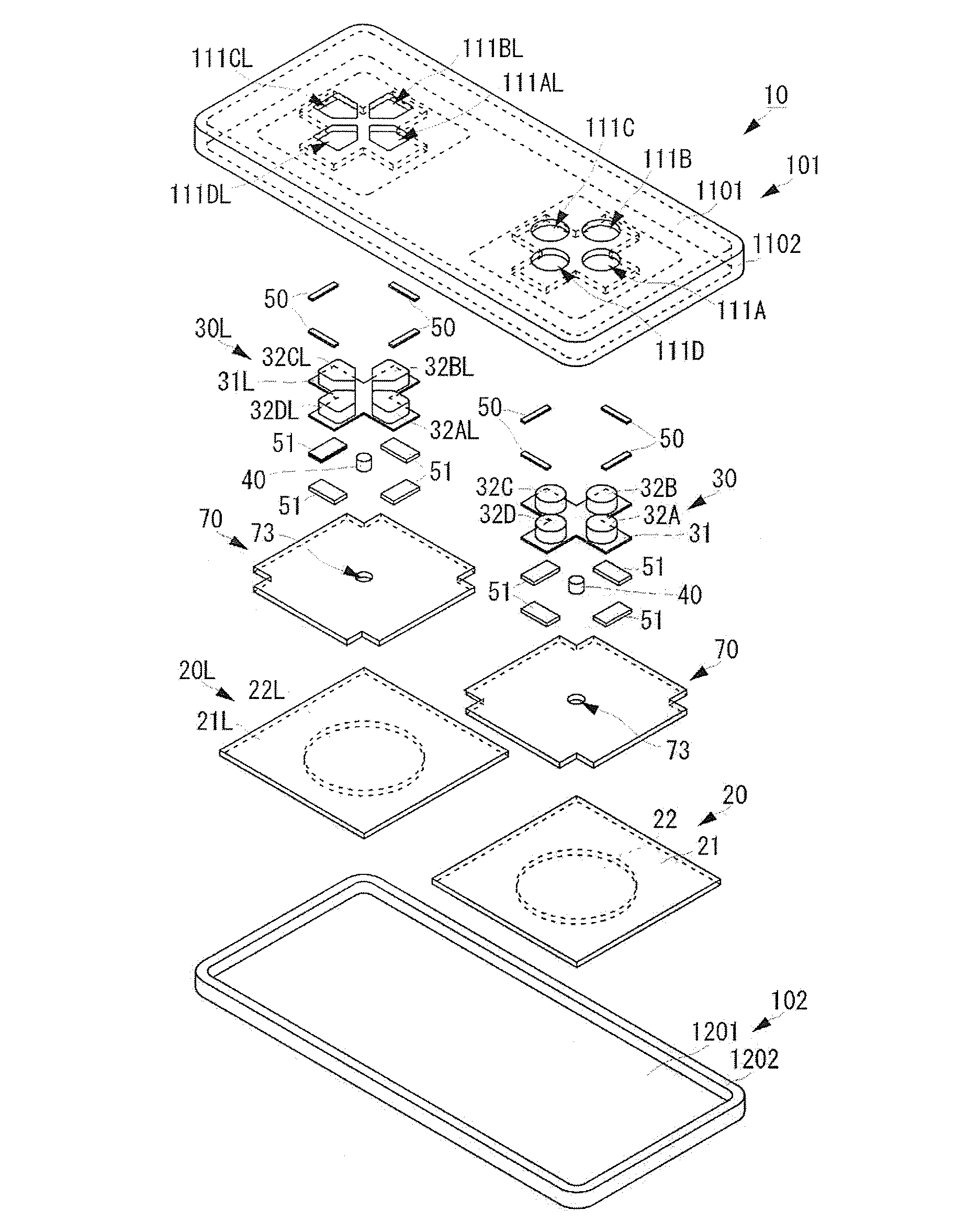
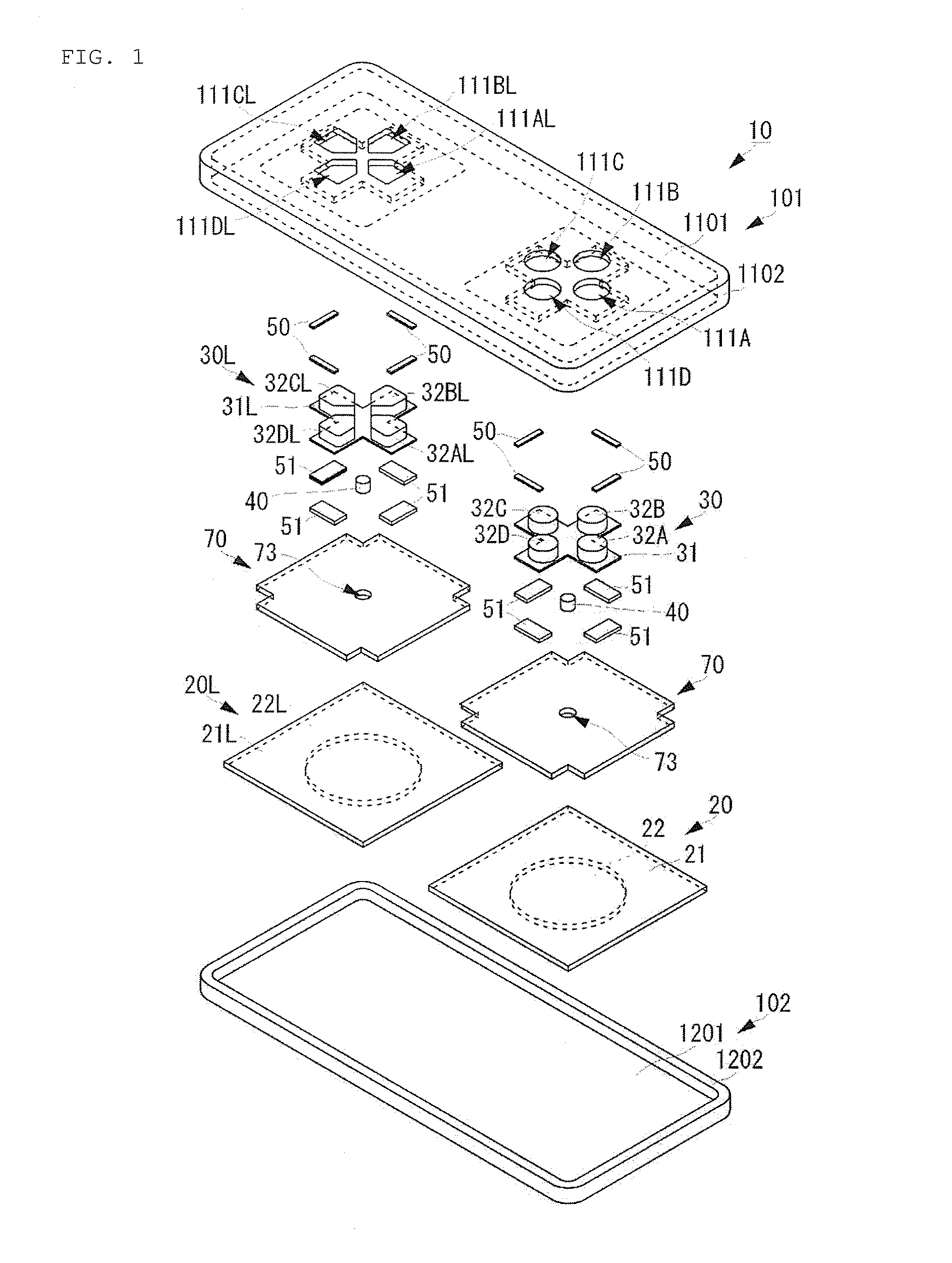
[0082]The actuators 20 and 20L should be mounted on the top surface chassis 101 by using the following structure. The description of the actuator 20L to which the same concept as the actuator 20 is applicable is omitted. FIG. 4 is an appearance perspective view of the actuator 20 structuring the tactile presentation device 10 according to the present invention.

[0083]The base substrate 21 of the actuator 20 is substantially square in plan view. The piezoelectric element 22 is circular in plan view. The center of the piezoelectric element 22 in plan view and the center of the base substrate 21 in plan view coincide with each other. In other words, the center of the piezoelectric element 22 in plan view and the center of the base substrate 21 in plan view coincide with the center of the actuator 20 in plan view.

[0084]Fixing through-holes 210 are formed in the base substrate 21. The fixing through-holes 210 are formed near four corners of the base substrate 21 in plan view. Distances R ...

second embodiment

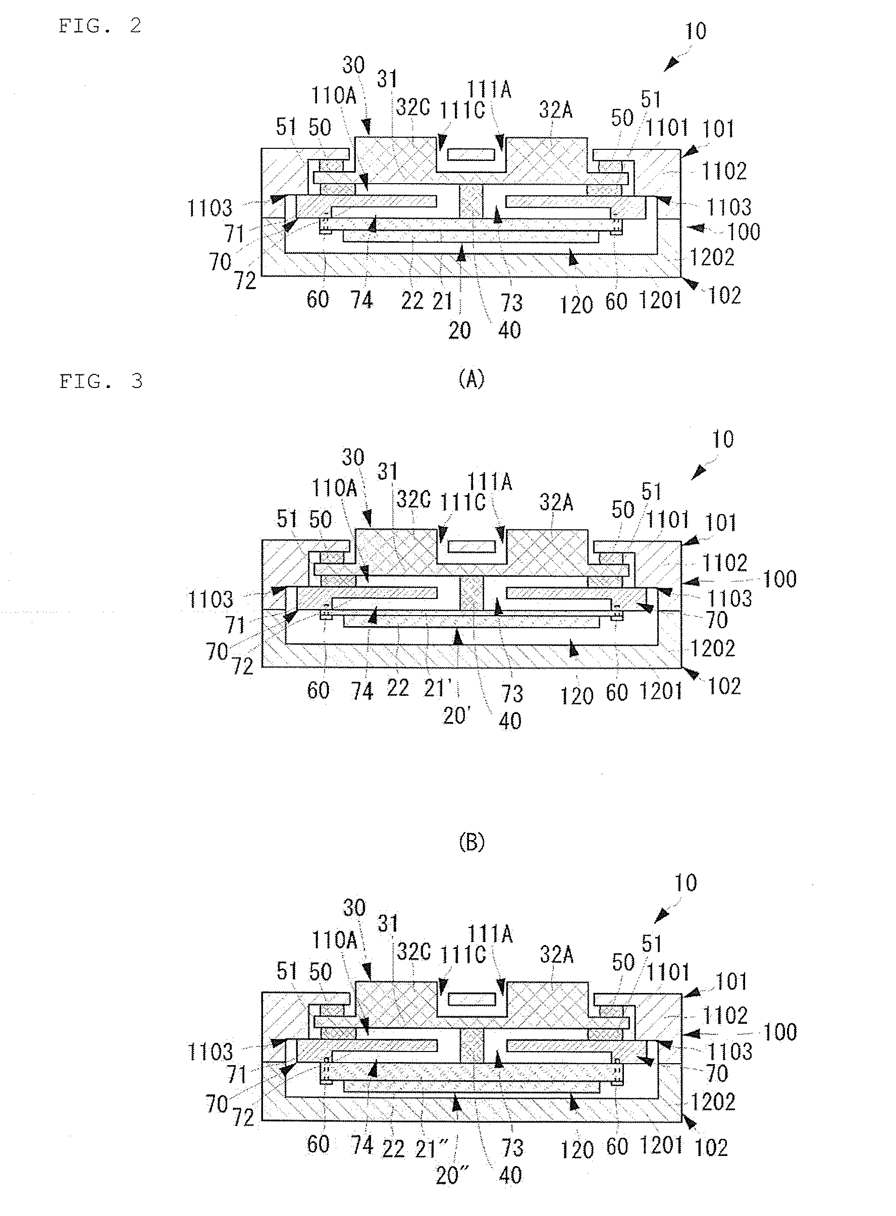
[0113]The reinforcement member 70B is planar like the reinforcement member 70, and has the outer peripheral portion 71 and the inner peripheral portion 72. The outer peripheral portion 71 and the inner peripheral portion 72 have different thicknesses so that the outer peripheral portion 71 is thicker than the inner peripheral portion 72. By this thickness difference, the recess 74 having a predetermined depth (height) is formed on one surface of the reinforcement member 70. The through-hole 73 is formed at the center of the reinforcement member 70B in plan view. In other words, the through-hole 73 is formed at the center of the inner peripheral portion 72. The reinforcement member 70B has a raised portion 720 surrounding the through-hole 73. The raised portion 720 has the same height as the interval between the planar surface of the reinforcement member 70B (the surface opposite to the base member 31 of the button type operation unit 30) and the surface of the base member 31 of the ...


PUM


Abstract

A tactile presentation device has a chassis having a top surface chassis, a bottom surface chassis, and an inner space, a button type operation unit fixed to the top surface chassis and having an operation surface, an actuator arranged in the inner space, and a vibration transmission member arranged between the actuator and the button type operation unit. The top surface chassis has a top surface having a top surface opening exposing the operation surface of the button type operation unit to outside, and a side surface formed along the peripheral edge of the top surface. The actuator is fixed to the side surface of the top surface chassis.

Description

CROSS REFERENCE TO RELATED APPLICATIONS[0001]The present application is a continuation of PCT / JP2012 / 083003 filed Dec. 20, 2012, which claims priority to Japanese Patent Application No. 2011-284816, filed Dec. 27, 2011, the entire contents of each of which are incorporated herein by reference.FIELD OF THE INVENTION[0002]The present invention relates to a tactile presentation device which provides a tactile sense to an operator according to an operation.BACKGROUND OF THE INVENTION[0003]Conventionally, various tactile presentation devices have been contrived which provide a tactile sense, such as vibration, to the finger of an operator according to an operation input when the finger of the operator directly touches an operation input unit, such as a touch panel or a button. For instance, Patent Literature 1 describes a portable electronic device as a tactile presentation device. The tactile presentation device has a basic structure as shown in FIG. 14. FIG. 14 is a cross-sectional vie...

Claims


Application Information

Patent Timeline
Patent Type & Authority Patents(United States)
IPC IPC(8): H01H3/60G06F3/0338H01H13/85G06F3/01
CPCH01H13/85G06F3/016G06F3/0338H01H2215/052G05G9/047A63F13/24A63F13/285
Inventor KAGAYAMA, KENJI
Owner MURATA MFG CO LTD
Why Eureka
Try Eureka