Tactile presentation device

Active Publication Date: 2014-10-16
MURATA MFG CO LTD
View PDF70 Cites 42 Cited by
  • Summary
  • Abstract
  • Description
  • Claims
  • Application Information

AI Technical Summary

Benefits of technology

[0030]In this structure, the number of components of the tactile presentation device can be reduced.
[0031]According to the present in

Problems solved by technology

Unlike the conventional tactile presentation device, in this structure, the problem that vibration cannot be transmitted to the touch panel without the actuator being contacted

Method used


Image

  • Tactile presentation device
  • Tactile presentation device
  • Tactile presentation device

Examples


first embodiment

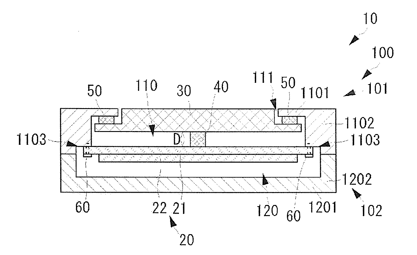
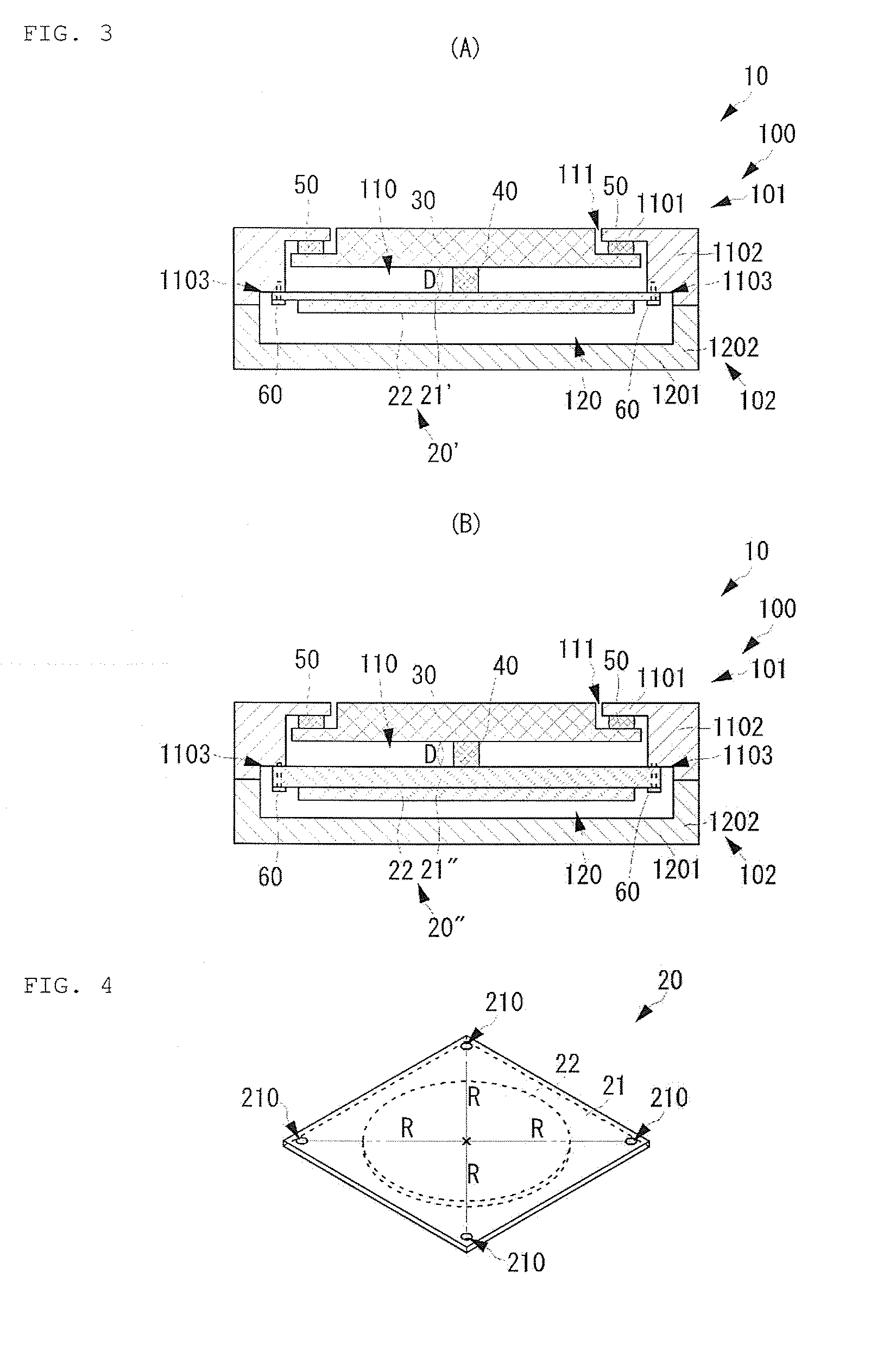
[0063]The actuator 20 should be mounted on the top surface chassis 101 by using the following structure. FIG. 4 is an appearance perspective view of the actuator 20 constituting the tactile presentation device 10 according to the present invention.

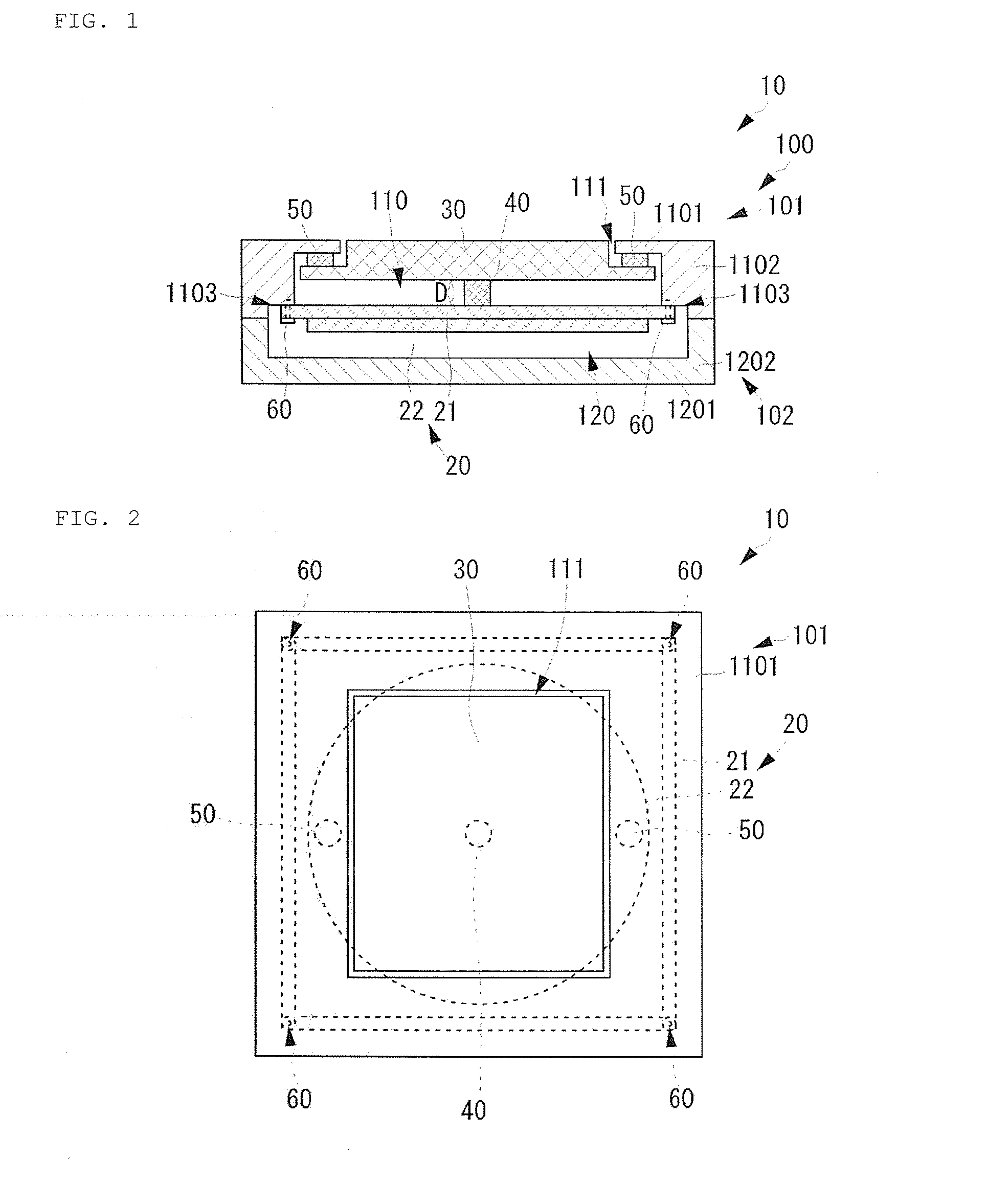
[0064]The base substrate 21 of the actuator 20 is substantially square in plan view. The piezoelectric element 22 is circular in plan view. The center of the piezoelectric element 22 in plan view and the center of the base substrate 21 in plan view coincide with each other. In other words, the center of the piezoelectric element 22 in plan view and the center of the base substrate 21 in plan view coincide with the center of the actuator 20 in plan view.

[0065]Fixing through-holes 210 are formed in the base substrate 21. The fixing through-holes 210 are formed near four corners of the base substrate 21 in plan view. Distances R from the center of the base substrate 21 in plan view to the fixing through-holes 210 are the same. The actuator 20...

second embodiment

[0090]The tactile presentation device 10B shown in FIG. 10 has almost the same structure as the tactile presentation device 10A except that a top surface chassis 101B which integrates the top surface chassis 101A of the tactile presentation device 10A with the reinforcement member 70 is provided.

[0091]In place of the chassis 100A of the tactile presentation device 10A according to the second embodiment, the tactile presentation device 10B has a chassis 100B including the top surface chassis 101B and the bottom surface chassis 102. The top surface chassis 101B integrates the top surface chassis 101A of the tactile presentation device 10A according to the second embodiment with the reinforcement member 70, and has the top surface 1101 and a side surface 1102B. Therefore, like the second embodiment, the top surface chassis 101B has a top surface inner space 110B formed by the top surface 1101 and the side surface 1102B. With such a structure, the mounting accuracy of the top surface c...

fourth embodiment

[0096]In the above embodiments, the actuator 20 is fixed to the top surface chassis 101 on the surface of the base substrate 21 on the side on which the piezoelectric element 22 is not arranged, but the structure as shown in FIG. 12 may be employed. FIG. 12 is a cross-sectional view showing the structure of a tactile presentation device 10F according to the present invention. FIG. 12 shows the cross section of the tactile presentation device 10F in a plane parallel to the side surface thereof.

[0097]The tactile presentation device 10F shown in FIG. 12 is different from the tactile presentation device 10 according to the first embodiment in that the structure of fixing the actuator to the top surface chassis is changed, and only the relevant portions will be described in detail. In place of the chassis 100 of the tactile presentation device 10 according to the first embodiment, the tactile presentation device 10F has a chassis 100C. The chassis 100C has a top surface chassis 101C, and...


PUM


Abstract

A tactile presentation device includes a chassis having a top surface chassis, a bottom surface chassis, and an inner space, a touch panel fixed to the top surface chassis and having an operation surface, an actuator arranged in the inner space, and a vibration transmission member arranged between the actuator and the touch panel. The top surface chassis includes a top surface having a top surface opening exposing the operation surface of the touch panel to outside, and a side surface formed along a peripheral edge of the top surface. The actuator is fixed to the side surface.

Description

CROSS REFERENCE TO RELATED APPLICATIONS[0001]The present application is a continuation of PCT / JP2012 / 083004 filed Dec. 20, 2012, which claims priority to Japanese Patent Application No. 2011-284817, filed Dec. 27, 2011, the entire contents of each of which are incorporated herein by reference.FIELD OF THE INVENTION[0002]The present invention relates to a tactile presentation device which provides a tactile sense to an operator according to an operation.BACKGROUND OF THE INVENTION[0003]Conventionally, various tactile presentation devices have been contrived which provide a tactile sense, such as vibration, to the finger of an operator according to an operation input when the finger of the operator directly touches an operation input panel, such as a touch panel. For instance, Patent Literature 1 describes a portable electronic device as a tactile presentation device. The tactile presentation device has a basic structure as shown in FIG. 13. FIG. 13 is a cross-sectional view showing t...

Claims


Application Information

Patent Timeline
IPC IPC(8): G06F3/01G06F3/041
CPCG06F3/016G06F3/041G06F3/017G06F3/03547
Inventor KAGAYAMA, KENJI
Owner MURATA MFG CO LTD
Why Eureka
Try Eureka