Connector

a technology of connecting device and connector, applied in the field of connecting device, can solve the problems of becoming expensiv

Active Publication Date: 2016-11-08
YAZAKI CORP
View PDF16 Cites 1 Cited by
  • Summary
  • Abstract
  • Description
  • Claims
  • Application Information

AI Technical Summary

Benefits of technology

[0014]With the first or second aspect of the present application, it is possible to provide a connector including: the first connector constituent including the first terminal and the locking part; and the second connector constituent including the second terminal and the locked part, the second terminal joined to the first terminal when the second connector constituent is installed in the first connector constituent, wherein the joining state between the first connector constituent and the second connector constituent is not cancelled so easily under condition that the second connector constituent is installed in the first connector constituent, whereby the fitting between the first terminal and the second terminal can be ensured.

Problems solved by technology

To sum up, the connector 501 of the first conventional example is complicated in structure and also hard to ensure the fitting, so that it becomes expensive.

Method used


Image

  • Connector
  • Connector
  • Connector

Examples


Embodiment Construction

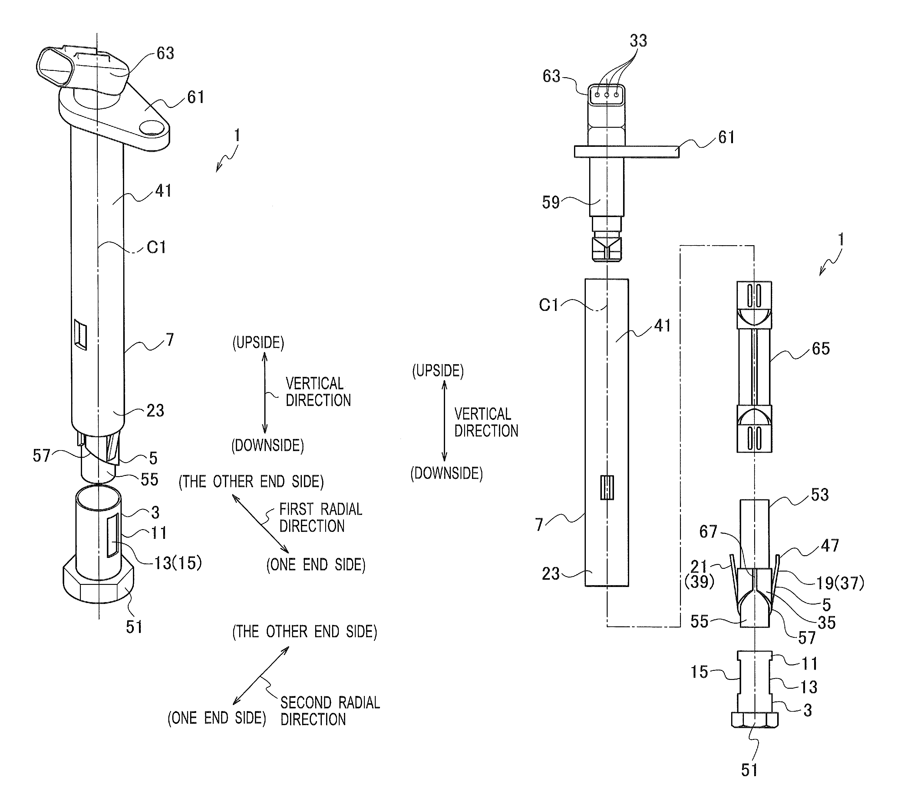
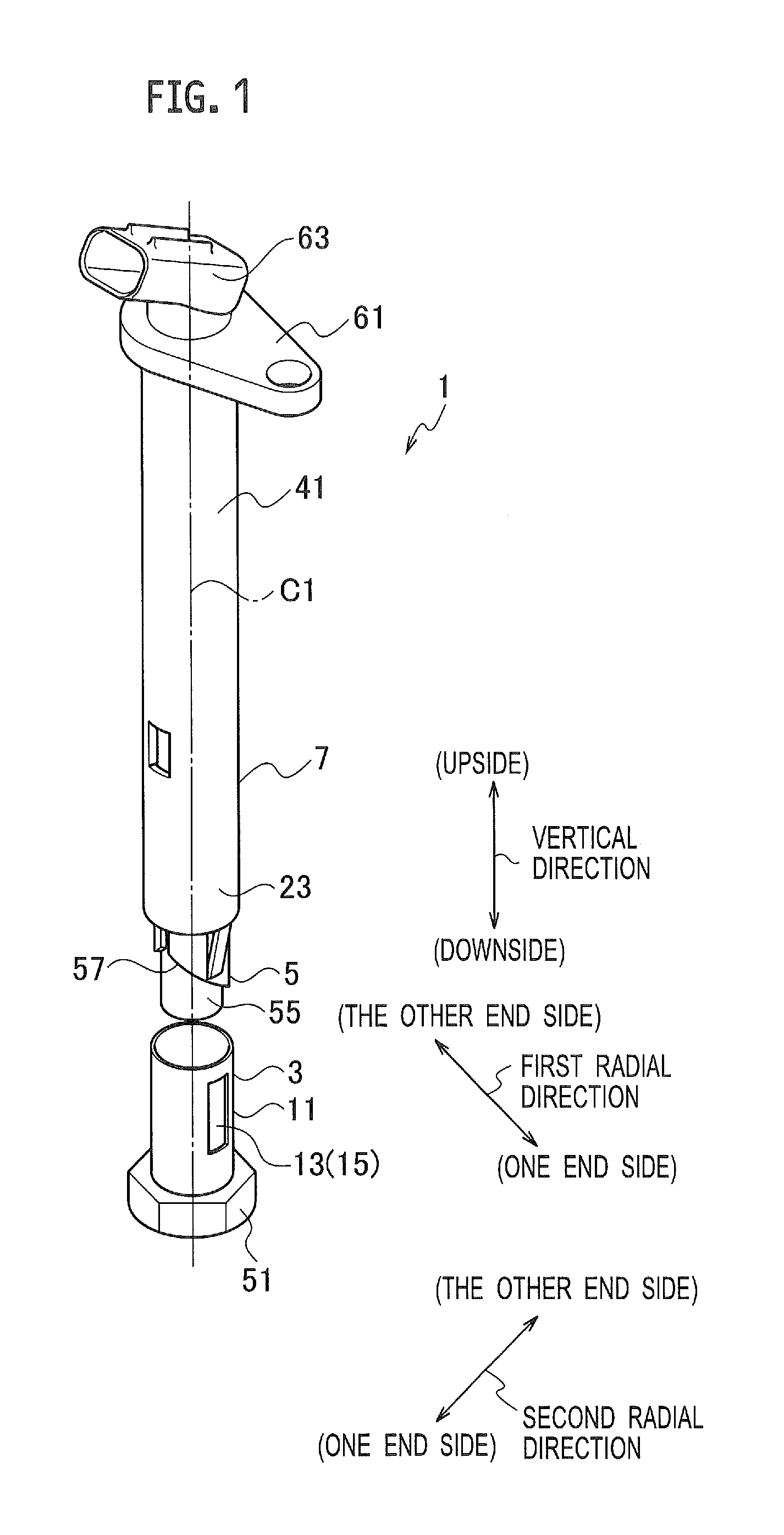
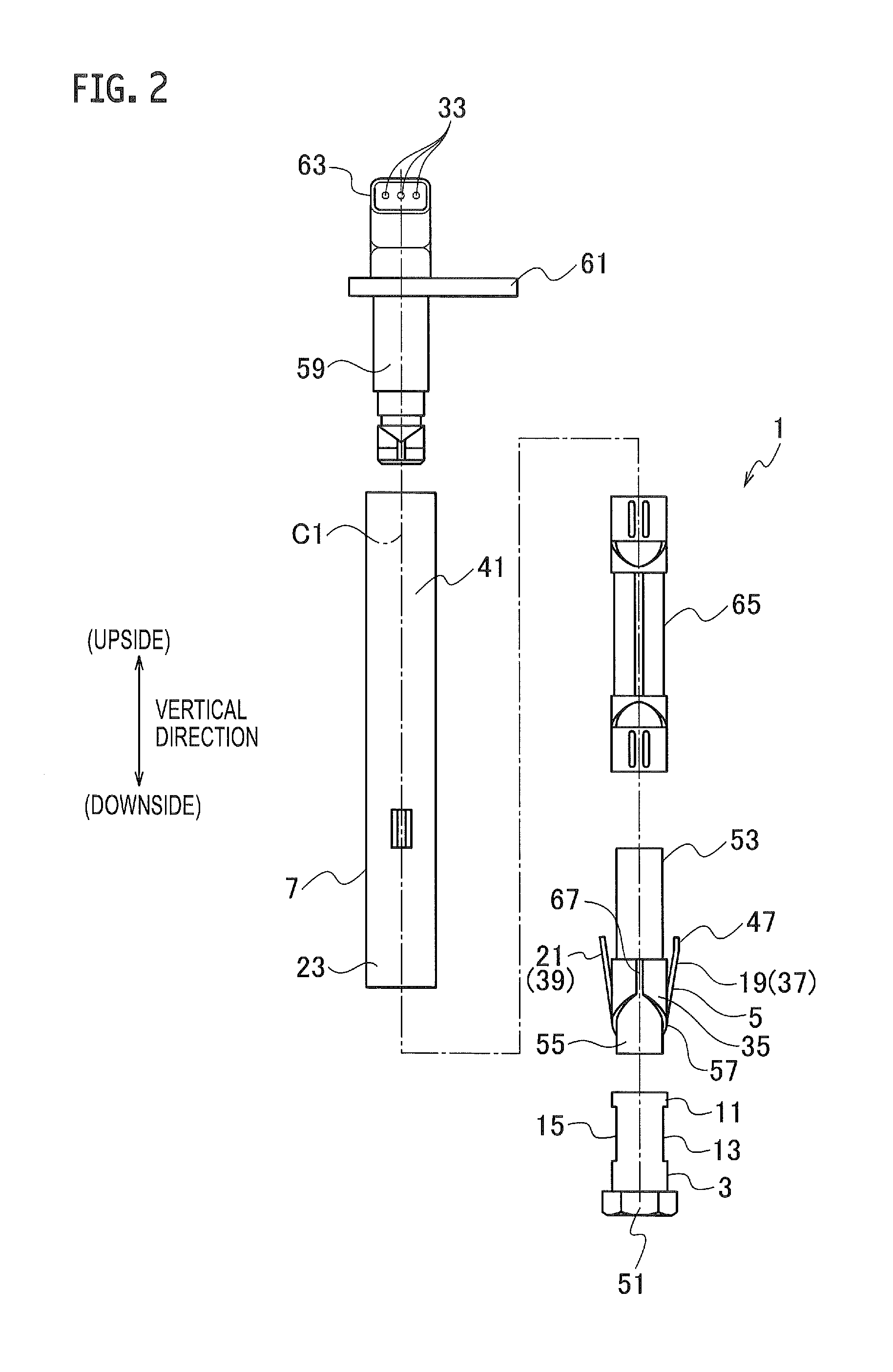
[0029]An embodiment of the present application will be described with reference to FIGS. 1 to 12. In use, a connector 1 according to the embodiment is installed in a casing of an equipment (for example, a cylinder head of an internal combustion engine such as a diesel engine) (not illustrated) integrally, and includes a first connector constituent 3, a second connector constituent 5, and a connector cover body 7.

[0030]The first connector constituent 3, such as a standby male connector, includes a first terminal 9 and a cylindrical part 11. The cylindrical part 11 is provided with a first locking part 13 and a second locking part 15. The first connector constituent 3 is installed in the casing of the equipment integrally.

[0031]In the first connector constituent 3, there is provided an ignition device (not illustrated), such as a glow plug such of a diesel engine. The first terminal 9 is composed of a plurality of male terminals. The first terminal 9 is electrically connected to the g...


PUM


Abstract

A connector includes: a first connector constituent including a first terminal and a cylindrical part provided with a first locking part and a second locking part; a second connector constituent provided with a second terminal, a first locked part, and a second locked part; and a connector cover body including a first cylindrical part provided with a first abutment part, and a second cylindrical part provided with a second abutment part, the second cylindrical part constituting a locked-part holding part. When the connector cover body is moved closer to the first connector constituent from a state in which the second connector constituent is installed in the connector cover body, the second connector constituent is joined to the first connector constituent.

Description

CROSS REFERENCE TO RELATED APPLICATIONS[0001]This application is a continuation of International Application No. PCT / JP2014 / 060288, filed Apr. 9, 2014, and based upon and claims the benefit of priority from Japanese Patent Application No. 2013-084600, filed Apr. 15, 2013, the entire contents of all of which are incorporated herein by reference.TECHNICAL FIELD[0002]The present application relates to a connector and more particularly, to a connector that accomplishes an electrical connection between terminals by engaging another connector constituent with a pair of connector forming bodies joined to each other.BACKGROUND ART[0003]There is known, as a first conventional example, a connector 501 illustrated in FIG. 13 (see US 2010 / 0003841 A1 (PTL 1)). The connector 501 of the first conventional example becomes costly since coaxially arranged contact components 503, 505, 507 are all exclusive parts. Additionally, when developing a structure which accomplishes fitting with a wire harness ...

Claims


Application Information

Patent Timeline
Patent Type & Authority Patents(United States)
IPC IPC(8): H01R13/627H01R13/502H01R13/639H01R43/26H01R13/64H01R13/506
CPCH01R13/502H01R13/6273H01R13/639H01R43/26H01R13/506H01R13/64
Inventor SEKINO, TETSUYA
Owner YAZAKI CORP
Why Eureka
Try Eureka