Pose determination from a pattern of four LEDs

a technology of pose determination and leds, applied in the field of computation, can solve the problems of inability to use, require a long time, and require effor

Active Publication Date: 2016-11-15
ASELSAN ELEKTRONIK SANAYI & TICARET ANONIM SIRKETI
View PDF6 Cites 8 Cited by
  • Summary
  • Abstract
  • Description
  • Claims
  • Application Information

AI Technical Summary

Problems solved by technology

However, we have two problems which each require a solution to the other problem to be correctly solvable.
Such an effort is necessary since it is possible that a tracked object may leave the view frustum of the camera then return to view.
Solving initial correspondence problems with the current methods require many frame captures, thus it requires a long time, whereas usage of methods that use pose of the tracked object can't be used since rotation / translation data of tracked object is not initially available.
The current methods do not offer an effective way of solving the initial correspondence problem.

Method used


Image

  • Pose determination from a pattern of four LEDs
  • Pose determination from a pattern of four LEDs
  • Pose determination from a pattern of four LEDs

Examples


Embodiment Construction

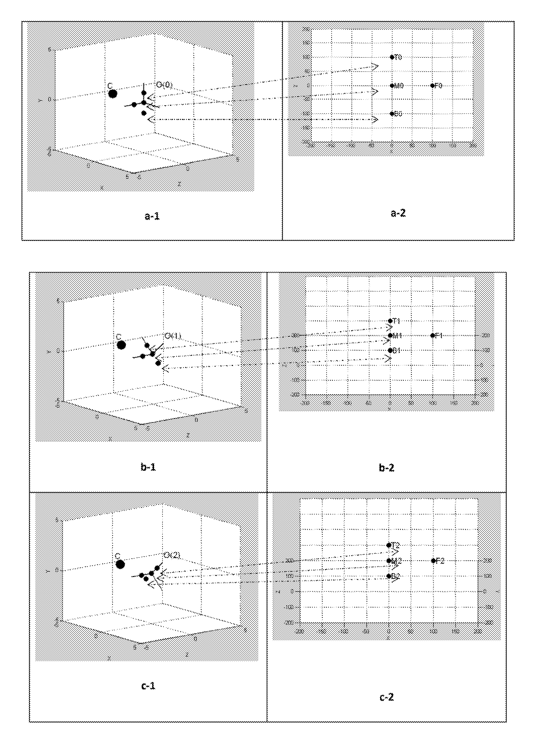
[0039]A method for solving correspondence problem (100) comprises the steps of,

Turning current LED group on (101),

Determining if all 4 LEDs in the current LED group are visible by camera (102),

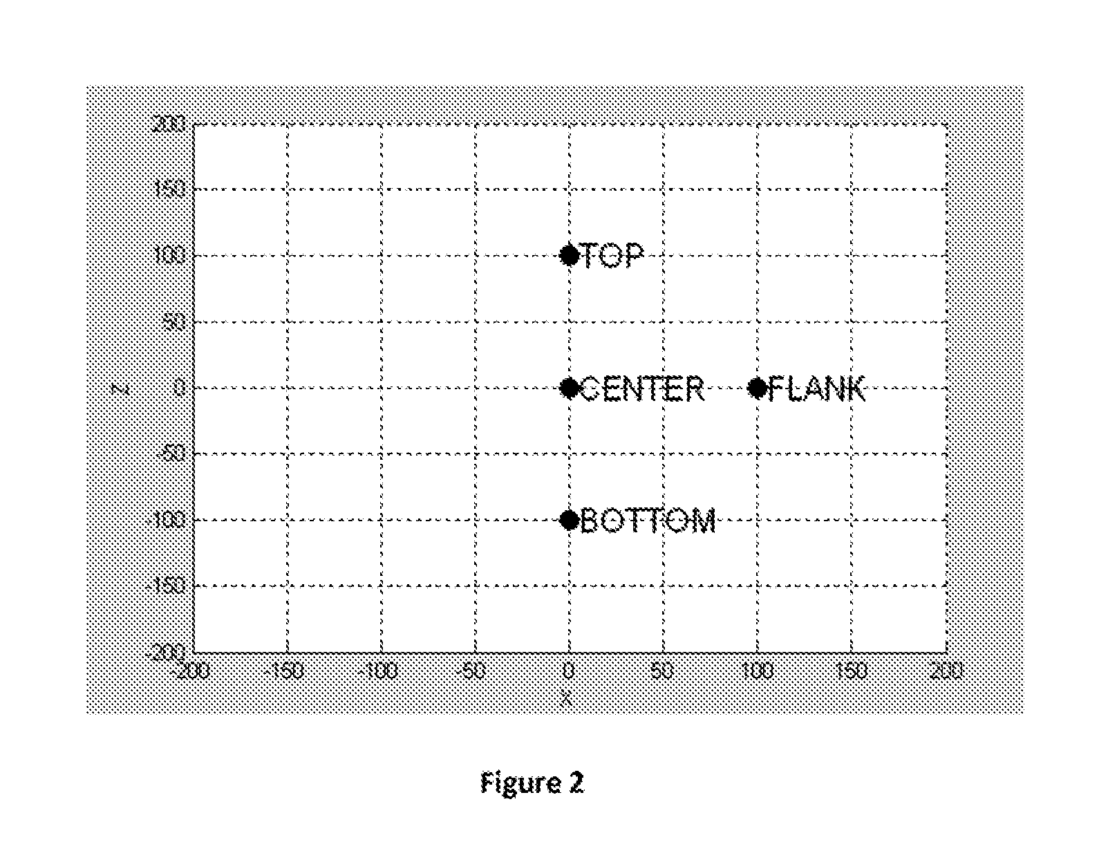
Identifying center LED if all the LEDs in the current LED group are visible (103),

Determining if the center LED is ambiguous (104),

Identifying flank LED if the center LED is not ambiguous (105),

Identifying the top and bottom LEDs (106),

Calculating the pose of tracked object using the calculated correspondences (107),

Determining if the calculated pose is ambiguous (108),

Switching to a new LED group if all the LEDs in the current LED group are not visible or the center LED is ambiguous or the calculated pose is ambiguous (109).

[0040]In step 101, we turn on LED in the current LED group so that their projections on 2D space can be seen. Each group preferably does consist of four LEDs selected in a particular pattern on the tracked object. Selection of the four LEDs to be lit stem from two main fac...


PUM


Abstract

The present invention relates to the field of computation and covers methods to find one to one mapping between fiducial markers on a tracked object and fiducial marker projections on the image plane captured by a camera in optical object tracking systems. A method for solving correspondence problem is realized to find correspondences between 3D points of an object and 2D projection of that object onto the image plane so that this can be used to find the object's 3D location and orientation. It is designed to work without current pose of the tracked object thus it is equally efficient on initial correspondence problem as correspondence problem. Furthermore, a method for selecting LED groups to be used for solving correspondence problem is also presented, which uses pose data representing possible poses of tracked object under working conditions thus LEDS groups are selected to satisfy use case requirements.

Description

FIELD OF THE INVENTION[0001]The present invention relates to the field of computation and covers methods to find one-to-one mapping between fiducial markers on a tracked object and fiducial marker projections on the image plane captured by a camera in optical object tracking systems.BACKGROUND OF THE INVENTION[0002]It is known that there are methods and models to track a three dimensional object in an environment and compute its position and orientation (pose) with respect to a predetermined coordinate system. These kinds of tracker systems are used, for example, in aircrafts to determine the orientation of a pilot's head. Once the orientation is acquired with respect to the coordinate system of a display devices, for example, then it is possible to generate graphics on these accordingly. There are different methods of tracking an object in a scene using magnetic, mechanical, or optical means. Currently, the spatial relations of objects may also be determined using magnetic sensors ...

Claims


Application Information

Patent Timeline
Patent Type & Authority Patents(United States)
IPC IPC(8): H04N5/225H04N5/235H04N5/222G06K9/00G06T7/00G06K9/20G06T7/20H04N5/228
CPCG06K9/00375G06K9/2027G06K9/2054G06T7/0042G06T7/2033H04N5/2256H04N5/2354G06T2207/10048G06T2207/30204G06T2207/30208G06T7/73G06T7/246G06V40/107H04N23/56H04N23/74
Inventor BICER, KADIR HAKANOKUYAN, ERKAN
Owner ASELSAN ELEKTRONIK SANAYI & TICARET ANONIM SIRKETI
Why Eureka
Try Eureka