Infusion pumps

a technology of infusion pump and plunger, which is applied in the direction of battery overheat protection, safety/protection circuit, instruments, etc., can solve the problems of inability to connect the plunger to the plunger and inability to apply a pulling force to the plunger

Active Publication Date: 2016-11-22
MEDTRONIC MIMIMED INC
View PDF326 Cites 24 Cited by
  • Summary
  • Abstract
  • Description
  • Claims
  • Application Information

AI Technical Summary

Benefits of technology

[0025]An infusion pump assembly in accordance with at least one of the present inventions includes a housing and an interlock. The housing may have a cartridge receiving area, a plunger pusher and a plunger drive mechanism. The interlock prevents removal of a medicament cartridge from the cartridge receiving area when the cartridge is in the inserted position and the plunger pusher is in a non-retracted position, and allows removal of the medicament cartridge from the cartridge receiving area when the cartridge is in the inserted position and the plunger pusher is a retracted position. The present inventions also include apparatus that comprise such a pump assembly in combination with a medicament cartridge, such a pump assembly in combination with a baseplate that can be attached thereto, and such a pump assembly in combination with a cannula, as such cartridges, baseplates and cannulas are described in the context of the examples herein, defined by the claims herein or known to those of skill in the art, as well as systems that comprise such a pump assembly in combination with two or more of a medicament cartridge, a baseplate and a cannula.
[0041]A method in accordance with at least one of the present inventions includes the steps of propelling a plunger pusher relative to the plunger of a medicament cartridge with a motor, and controlling motor torque such that the torque is continuously within a range having a lower limit that is sufficient to overcome stiction of the cartridge plunger and move the plunger and an upper limit that is low enough so as to not cause leakage past plunger seals due to excessive pressure in the cartridge reservoir.

Problems solved by technology

The pusher may be unconnectable to the plunger and incapable of applying a pulling force to the plunger.

Method used


Image

  • Infusion pumps
  • Infusion pumps
  • Infusion pumps

Examples


Embodiment Construction

[0183]The following is a detailed description of the best presently known modes of carrying out the inventions. This description is not to be taken in a limiting sense, but is made merely for the purpose of illustrating the general principles of the inventions.

[0184]The detailed description of the exemplary embodiments is organized as follows:

[0185]I. Introduction

[0186]II. Exemplary System Overview

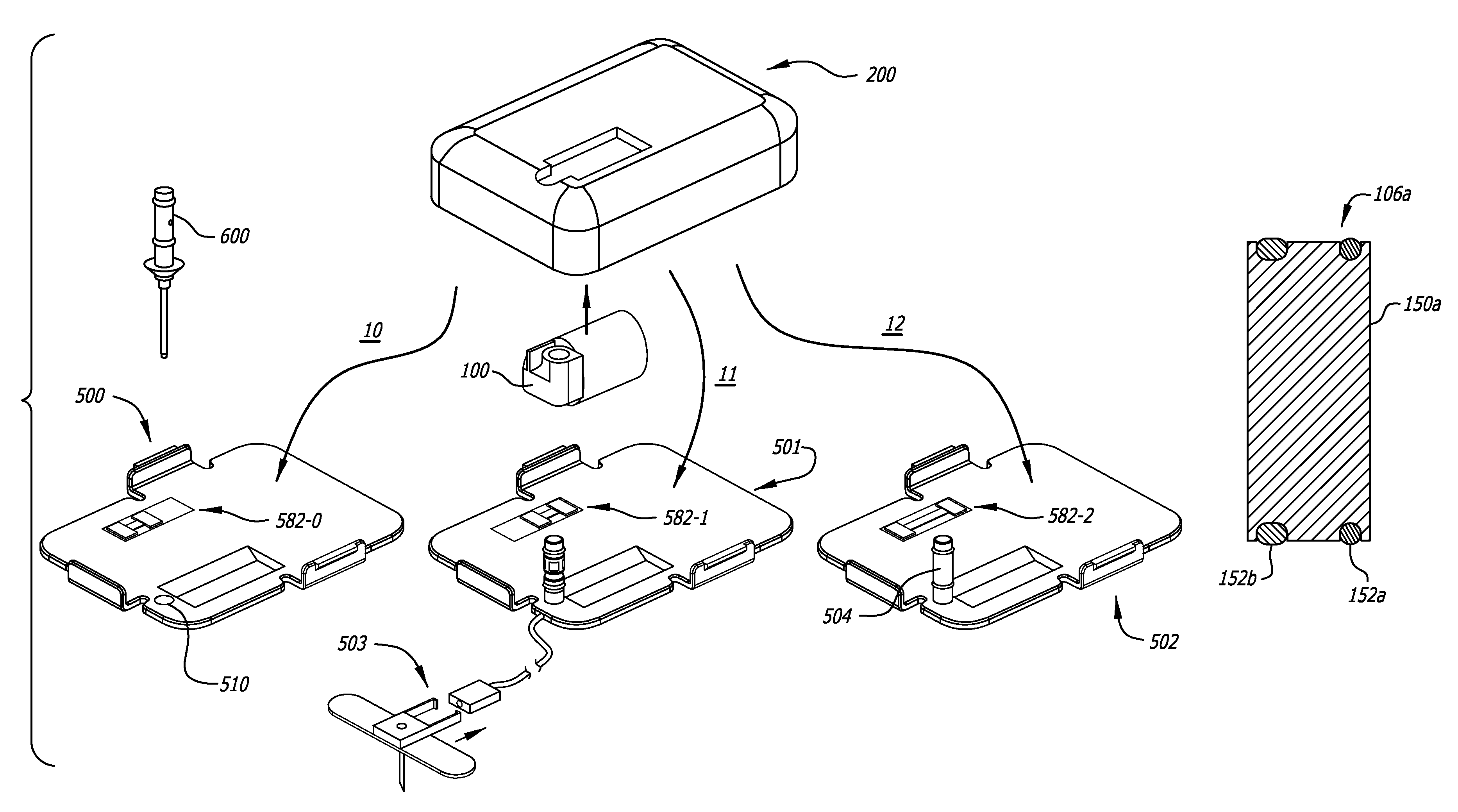
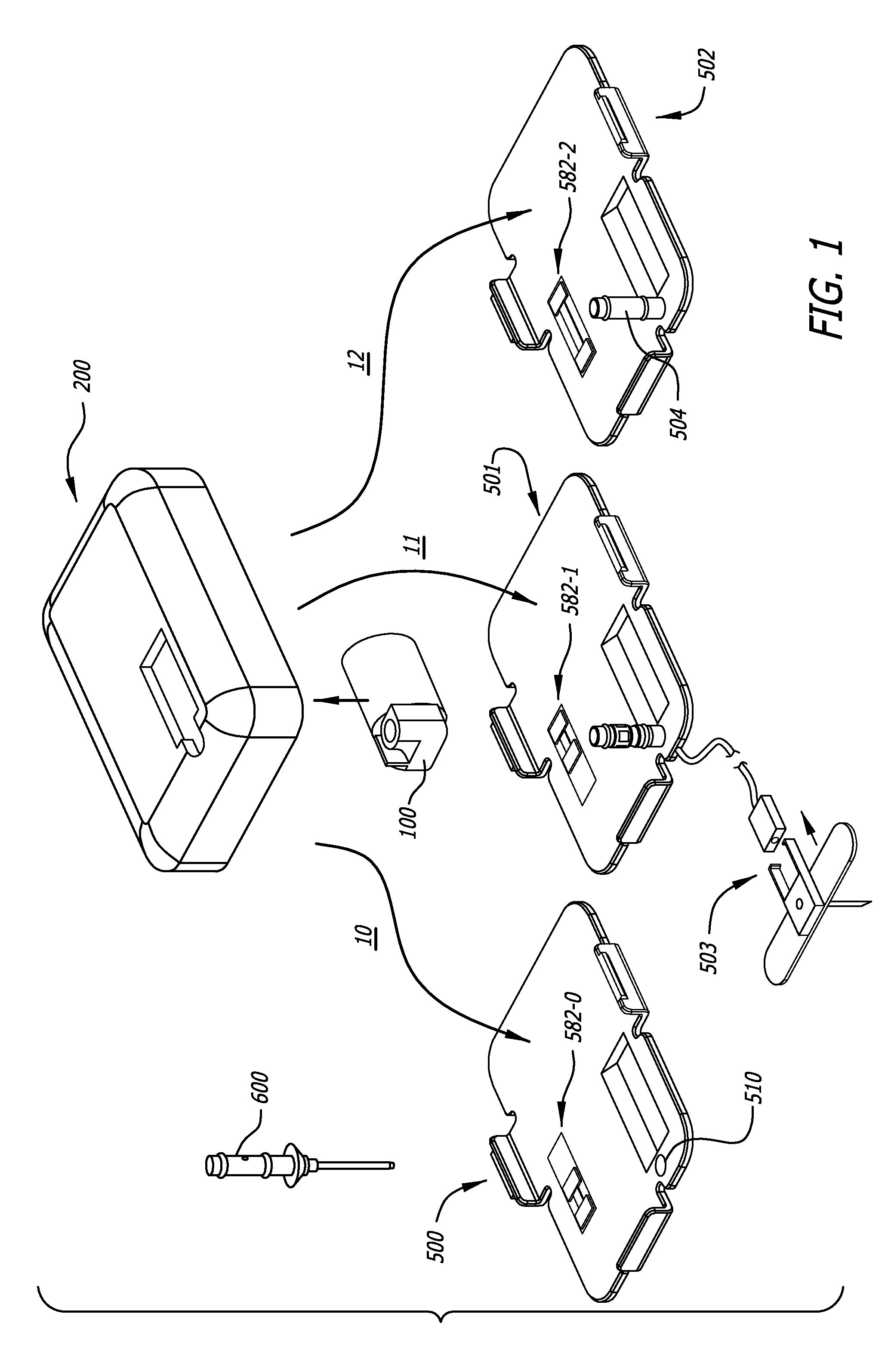
[0187]III. Exemplary Medicament Cartridges

[0188]IV. Exemplary Pump Assemblies[0189]A. Exemplary Housings[0190]B. Exemplary Pump Modules Overview[0191]C. Exemplary Chassis[0192]D. Exemplary Plunger Pushers and Drive Mechanisms[0193]E. Exemplary Reservoir Clamping[0194]F. Exemplary Cartridge Lock and Bias Apparatus[0195]G. Exemplary Encoders[0196]H. Exemplary Pressure / Occlusion Sensors[0197]I. Exemplary Fall-Off Detectors[0198]J. Exemplary Batteries and Battery Rechargers[0199]K. Exemplary Alarms[0200]L. Exemplary System Controllers[0201]M. Exemplary Motor Control

[0202]V. Exemplary Baseplate...


PUM


Abstract

Ambulatory infusion pumps, pump assemblies, cartridges, baseplates, cannulas, insertion tools, and related components as well as combinations thereof and related methods.

Description

BACKGROUND[0001]1. Field[0002]The present devices and methods relate generally to ambulatory infusion pumps.[0003]2. Description of the Related Art[0004]Ambulatory infusion pumps (also referred to herein simply as “infusion pumps”) are relatively small, at least substantially self-contained devices that are used to introduce drugs and other infusible substances (collectively “medicament”) into patients' bodies. Some infusion pumps are configured to be worn on a belt or carried in a clothing pocket. Other infusion pumps are configured to be adhered to skin in patch-like fashion. Infusion pumps are advantageous in that they may be used to, for example, subcutaneously introduce (or “infuse”) medicament on an ongoing or even continuous basis outside of a clinical environment. Infusion pumps are also advantageous in that they greatly reduce the frequency of subcutaneous access events such as needle-based shots. One example of a medicament that may be introduced by an infusion pump is a l...

Claims


Application Information

Patent Timeline
Patent Type & Authority Patents(United States)
IPC IPC(8): A61M5/142A61M5/168A61M5/145H02J7/00A61M5/14A61M5/158
CPCA61M5/14216A61M5/1452A61M5/14248A61M5/16804H02J7/0044H02J7/0091A61M2205/3365A61M2205/3368A61M2205/3372A61M2205/50A61M2205/502A61M2205/52A61M2205/6027A61M2205/6054A61M2205/6063A61M2205/8206A61M2205/8237H02J2007/0037A61M5/1413A61M5/14546A61M5/1684A61M5/16854A61M2005/1402A61M2005/14252A61M2005/14268A61M2005/1585A61M2005/16863A61M2005/16868A61M2205/073A61M2205/12A61M2205/13A61M2205/14A61M2205/18A61M2205/276A61M2205/3306A61M2205/3317H02J7/00302H02J7/0029H02J7/007192H02J7/00309H02J2310/23
Inventor SMITH, ROGER E.CAUSEY, JAMESGIBSON, SCOTT R.RING, LAWRENCE SCOTT
Owner MEDTRONIC MIMIMED INC
Why Eureka
Try Eureka