
Method of controllably directing a device into a human vessel

a controllable and human-vessel technology, applied in the field of surgical procedures, can solve the problems of excessive radiation exposure, increased contrast volume, and increased catheter manipulation

Active Publication Date: 2016-11-22
FRONTIER MEDICAL DEVICES
View PDF9 Cites 0 Cited by
  • Summary
  • Abstract
  • Description
  • Claims
  • Application Information

AI Technical Summary

Benefits of technology

The invention is a method for controllably directing a device into a vessel network in a human body to access a target site. The method involves obtaining a tubular component with a tubular wall that bounds a passageway and has an aperture at its end. An introducing member is then directed into the vessel network towards the target site while the tubular component is placed in an operative relationship with the introducing member. The introducing member and tubular component are relatively moved between a first relationship where the introducing member blocks the aperture and a second relationship where the aperture is at least partially opened. The method also involves guiding a guide wire into the vessel network and using it to direct the device into the target site. The invention provides a way to safely and accurately direct the device to the target site.

Problems solved by technology

With existing technology, may procedures may require excessive catheter manipulation in the aortic domain.
Such catheter manipulations can be cumbersome and endanger the patient because of embolic events, potentially leading to stroke.
In situations of unfavorable aortic arch anatomy, contrast volume may be increased, radiation exposure can be excessive, and procedural time may be undesirably prolonged.
The procedural risk of stroke and contrast nephropathy may increase while the total radiation exposure to both patient and surgical personnel may multiply.
This is particularly true with unfavorable aortic arch anatomy.
At best, conventional procedures rely upon a relatively unstable platform for the introduced device with success in accessing target vessels often becoming hit or miss based upon a number of variables involved, including experience, anatomical conditions, etc.

Method used


Image

  • Method of controllably directing a device into a human vessel
  • Method of controllably directing a device into a human vessel
  • Method of controllably directing a device into a human vessel

Examples


Embodiment Construction

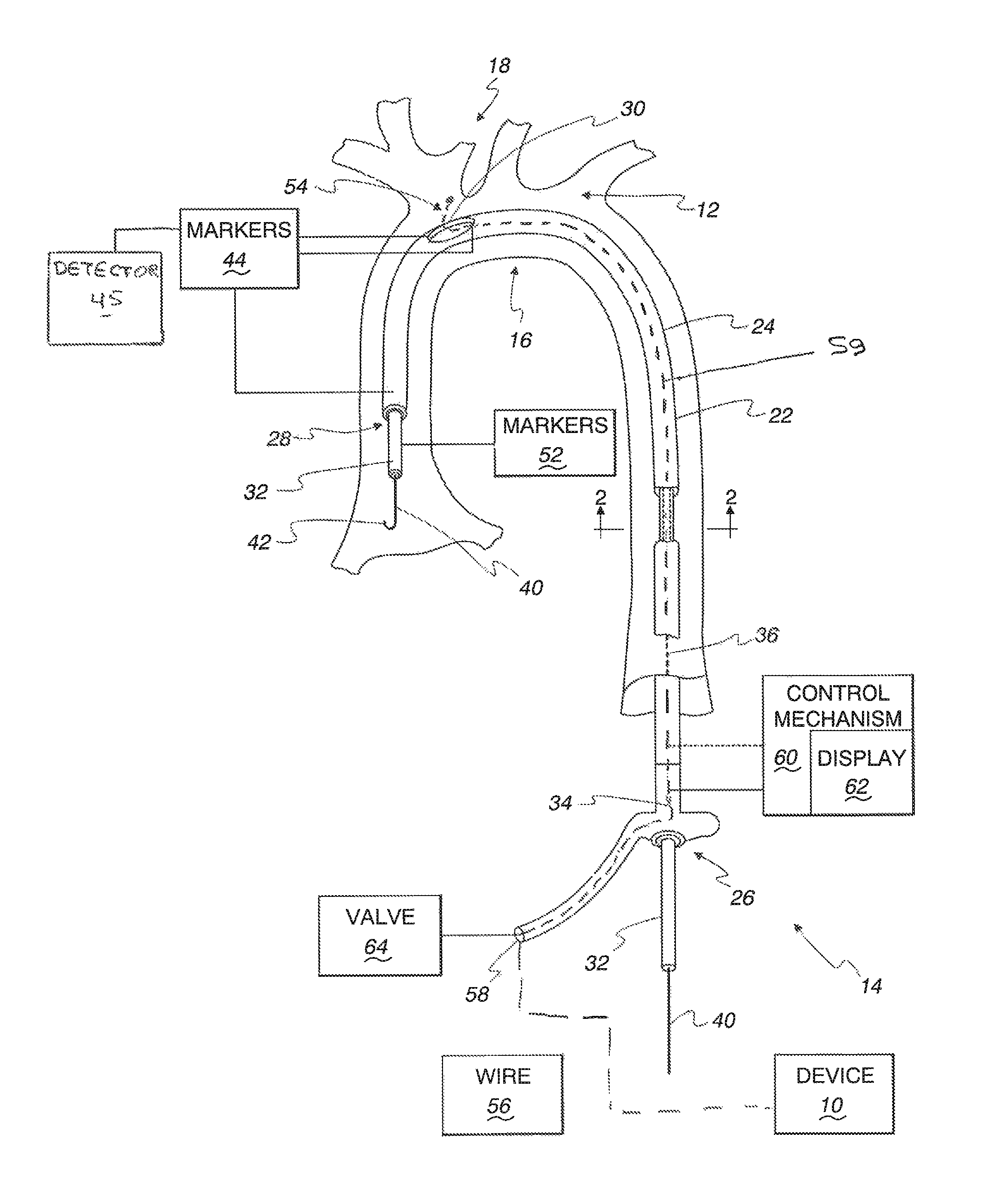
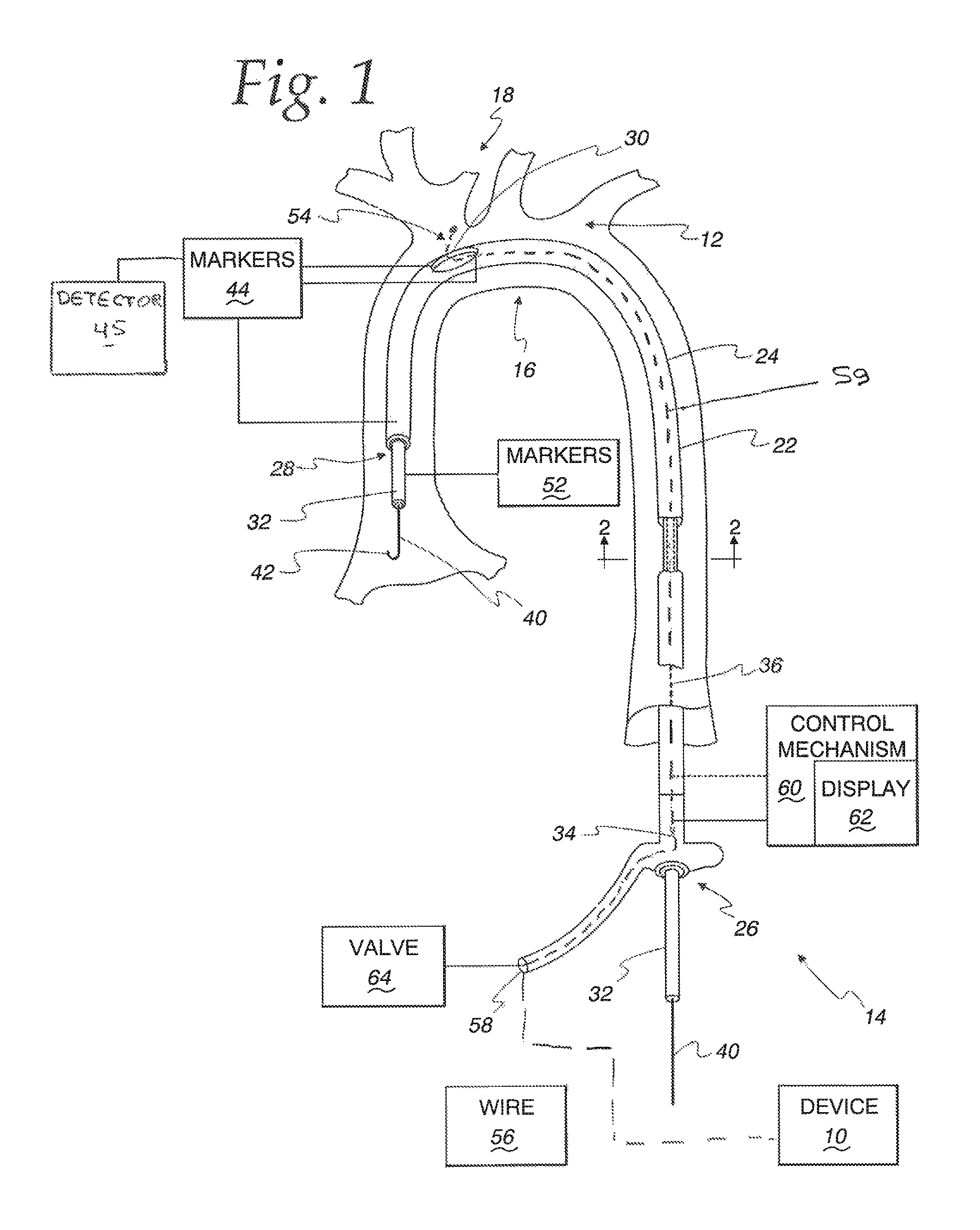
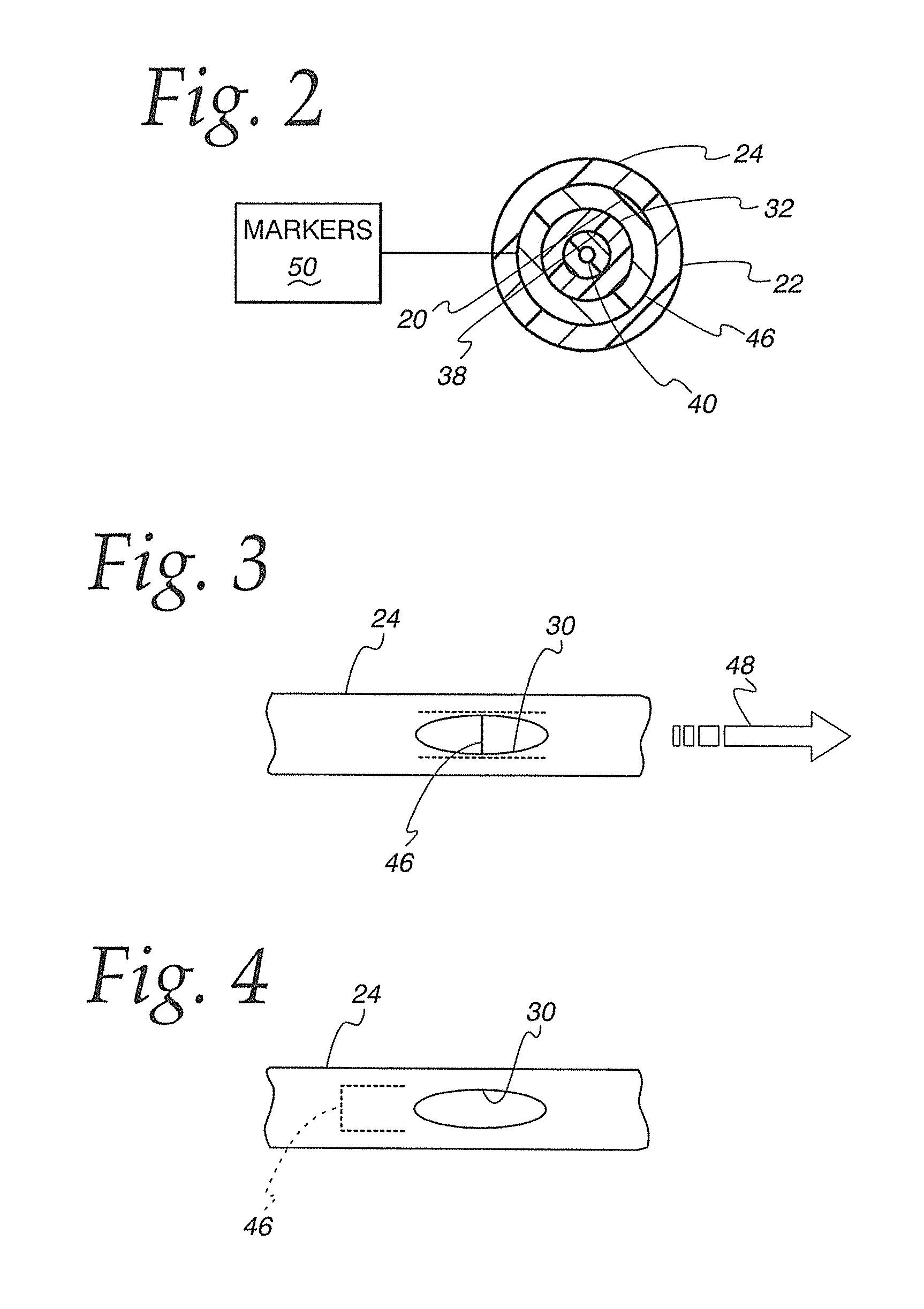
[0037]Referring initially to FIGS. 1-4, one form of system for controllably directing a device 10 to a target site in a vessel network 12 in a human body, is shown generally at 14. It should be understood that the system 14 is usable in any human or non-human vessel network, but has particular utility in the region of the aortic arch at 16, wherein the target site is in one or more of the vessels at 18 leading to a patient's head or neck.

[0038]Further, the nature of the device 10 is not limited other than by the fact that it is desirably introducible into a passageway 20 bounded by a tubular wall 22 on a tubular component 24. The tubular wall 22 has a length between proximal and distal ends 26, 28, respectively. An elongate aperture 30 is formed through the tubular wall 22 between the ends 26, 28.

[0039]The system 14 further includes an introducing member 32. The introducing member 32 and tubular component 24 are placed in an operative relationship with at least a portion of the intr...


PUM


Abstract

A method of controllably directing an elongate device into a vessel network including the steps of: obtaining a tubular component with a tubular wall bounding a passageway and having an aperture between spaced ends; directing an introducing member into the vessel network towards a target site; placing the introducing member and tubular component in an operative relationship wherein at least a portion of the introducing member resides within the passageway; relatively repositioning the introducing member and tubular component by guided movement, one against the other, to place the aperture at an introduction location; and directing the device through the passageway to and through the aperture to the target site.

Description

CROSS-REFERENCE TO RELATED APPLICATIONS[0001]This application is a continuation-in-part of U.S. application Ser. No. 14 / 185,764, filed Feb. 20, 2014.BACKGROUND OF THE INVENTION[0002]Field of the Invention[0003]This invention relates to surgical procedures and, more particularly, to a method of directing a device into a human vessel, as at the aortic arch.[0004]Background Art[0005]Current catheters are limited by geometry at the aortic arch and by individual patient anatomical variations. Access into the carotid vessels oftentimes requires catheter manipulation in the aorta and in the proximal common carotid vessels. With existing technology, may procedures may require excessive catheter manipulation in the aortic domain. Such catheter manipulations can be cumbersome and endanger the patient because of embolic events, potentially leading to stroke. In situations of unfavorable aortic arch anatomy, contrast volume may be increased, radiation exposure can be excessive, and procedural t...

Claims


Application Information

Patent Timeline
Patent Type & Authority Patents(United States)
IPC IPC(8): A61M25/01A61M25/09
CPCA61M25/0113A61B2090/3966A61M25/0108A61M2210/127
Inventor GENCHEFF, NELSON E.
Owner FRONTIER MEDICAL DEVICES
Learn More