Triple locking hook connector

a technology of locking hooks and connectors, applied in the direction of fastening means, life-saving devices, safety belts, etc., can solve the problems of hardly constructing a completely secure protection, affecting so as to reduce the concern of unhooking, improve the safety of use, and reduce the effect of unhooking

Active Publication Date: 2016-11-22
AEROHOOK TECH +1
View PDF26 Cites 13 Cited by
  • Summary
  • Abstract
  • Description
  • Claims
  • Application Information

AI Technical Summary

Benefits of technology

[0016]Accordingly, the three-part mode for opening the hook opening of the present invention is certainly able to further enhance the safety of use of the present invention, which is enough for dealing with the complicated operating circumstances of the upper air and reducing the concern of unhooking caused by unintended contact to the lowest. Besides, when the locking bar that is locking the hook opening is side bumped, the locking bar can pass the stress to the hook through the spacing portion and the first bolt, so the present invention really has an advancement of dispersing stress, which allows the present invention to enlarge the hook opening and lengthen the locking bar in the manner that the requirements for structural safety are also met, so that the operations of hooking and unhooking are made to be more smooth and efficient.

Problems solved by technology

According to the most advancing safety hook disclosure by U.S. Pat. No. 8,117,721, such conventional case, however, still has the following disadvantages to be improved.
First, this prior case simply controls whether a locking bar can turn to open a hook hole via the operation on a controlling shaft, which structure still belongs to the scope of double locking hook connector and, therefore, has a misgiving of unhooking due to an unintended contact to the controlling shaft under operating circumstances of the complicated upper air.
As a result, this prior case can hardly construct a completely secure protection.
Second, when the locking bar of this prior case is under side bump, it can only simply transfer the bumping force to the hook, which easily converges the stress and causes a great restriction on the length of the locking bar, so the hook opening cannot correspondingly be enlarged.
As a result, when a user is proceeding to hook or unhook, either action can be finished at once, which increases trouble with the operation.

Method used


Image

  • Triple locking hook connector
  • Triple locking hook connector
  • Triple locking hook connector

Examples


Embodiment Construction

[0025]The following description is disclosed to enable any person skilled in the art to make and use the present invention. Preferred embodiments are provided in the following description only as examples and modifications will be apparent to those skilled in the art. The general principles defined in the following description would be applied to other embodiments, alternatives, modifications, equivalents, and applications without departing from the spirit and scope of the present invention.

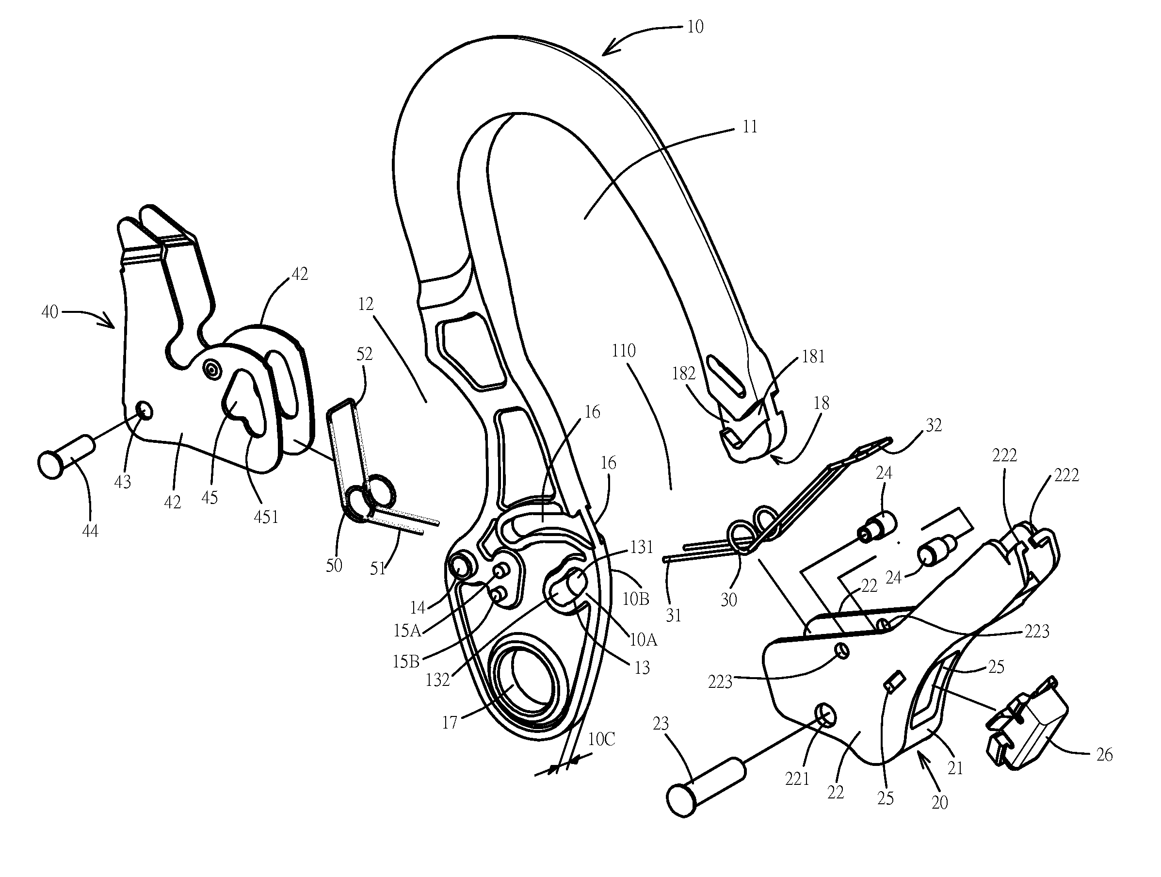
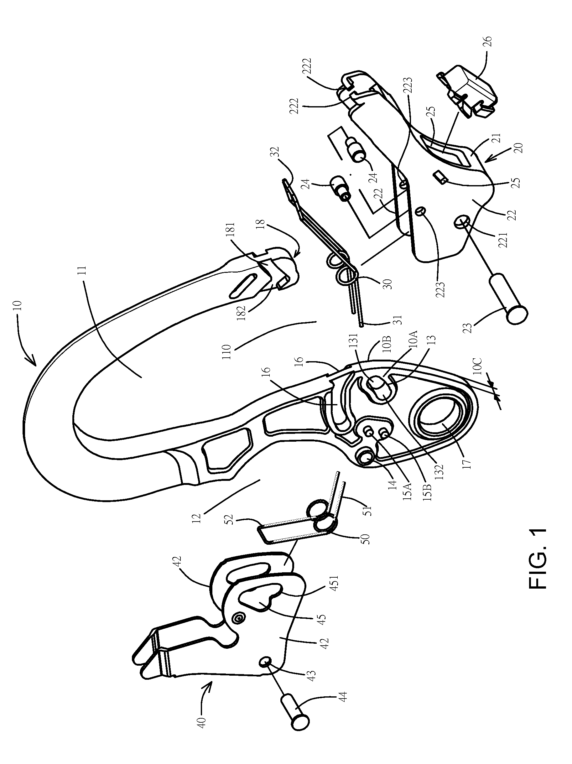
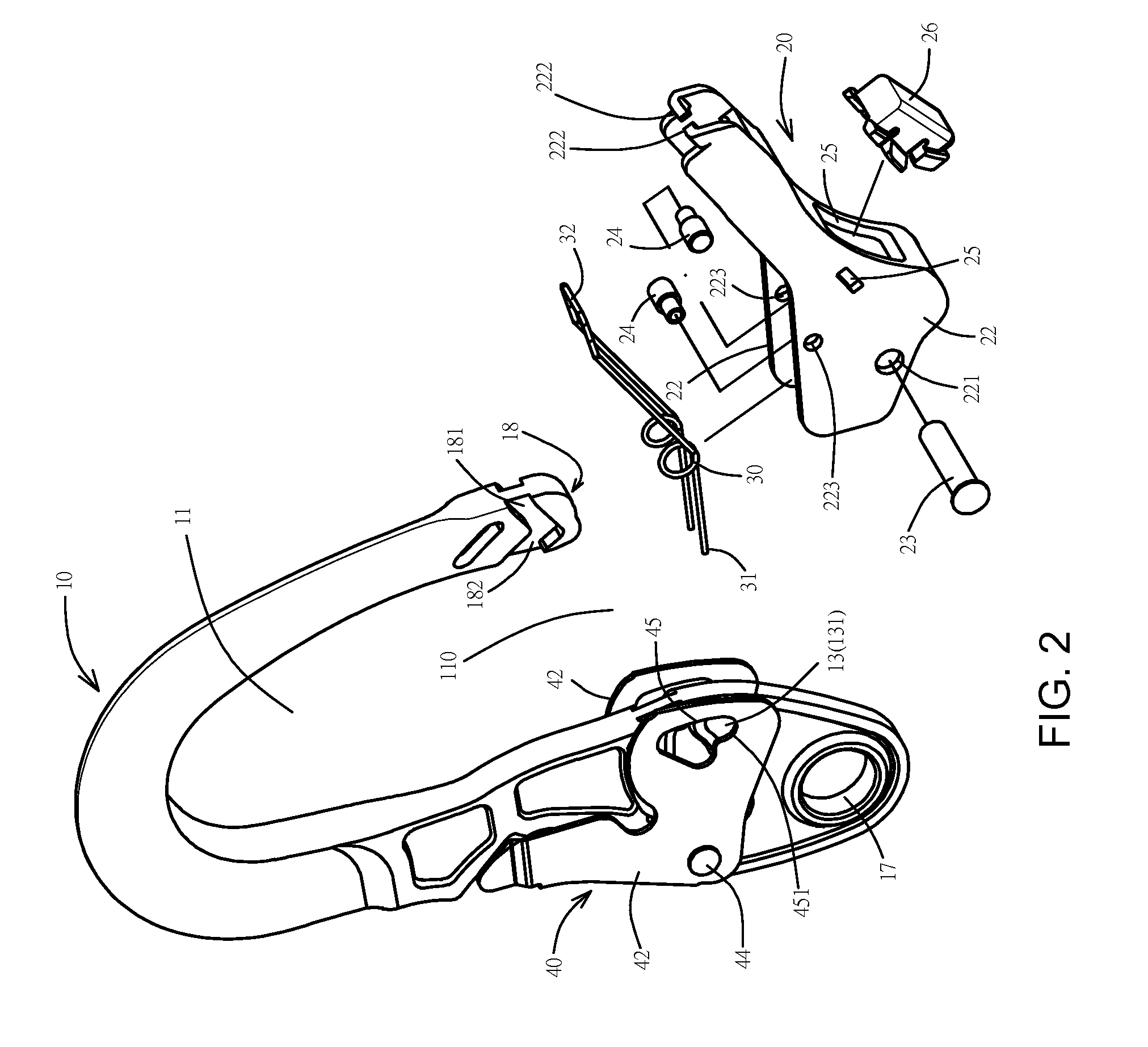
[0026]Please refer to FIGS. 1 to 8, the present invention comprises the following:

[0027]A hook 10 comprises a thickness 10C defined between a front side 10A and a back side 10B. A hook hole 11 penetrates the thickness 10C, wherein a side of the hook 10 has a hook opening 110 linking through the inside and outside of the hook hole 11. The hook 10 dentedly has a containing groove 12 penetrating the thickness 10C on an edge of an end of the hook opening 110. The hook 10 spacingly has an axle hole 14...


PUM


Abstract

A triple locking hook connector includes a hook, a locking bar, a first spring, a controlling shaft, and a second spring. The hook has an axle hole and a first groove on an end of a hook opening, and has a spacing portion on the other end of the hook opening. An edge of an end of the locking bar has a first bolt. The first spring is to drive a first bolt to keep at the first position and to drive the other end of the locking bar to remain in the spacing portion. The controlling shaft joins the axle hole via a main axle to restrict the first bolt in the first position and to be driven by a second spring to stay at the third position to ensure the locking bar shutting the hook opening.

Description

NOTICE OF COPYRIGHT[0001]A portion of the disclosure of this patent document contains material which is subject to copyright protection. The copyright owner has no objection to any reproduction by anyone of the patent disclosure, as it appears in the United States Patent and Trademark Office patent files or records, but otherwise reserves all copyright rights whatsoever.BACKGROUND OF THE PRESENT INVENTION[0002]1. Field of Invention[0003]The present invention provides a triple locking hook connector, in particular, a new technique that a hook hole can only be opened by sequentially operating a controlling shaft to release a locking bar, pulling the locking bar out of a spacing portion, and then forcing the locking bar to turn toward the hook hole. The concern of unhooking can be further reduced to the lowest with this whole new design.[0004]2. Description of Related Arts[0005]In rock climbing, mountain climbing, building construction, and the like contexts that require ascending and ...

Claims


Application Information

Patent Timeline
Patent Type & Authority Patents(United States)
IPC IPC(8): F16B45/02A63B29/02A62B35/00
CPCF16B45/02A62B35/0037A63B29/02F16B45/028F16B45/023F16B45/026
Inventor YANG, KAI CHIEHLAI, TZU-SEN
Owner AEROHOOK TECH
Why Eureka
Try Eureka