Firearm sound and flash suppressor having low pressure discharge

a suppressor and low-pressure technology, applied in the field of suppressors, can solve the problems of threaded connections becoming difficult to separate, baffles, chambers and threads being clogged, and baffles typically becoming fouled

Inactive Publication Date: 2016-11-22
LARUE MARK C
View PDF25 Cites 60 Cited by
  • Summary
  • Abstract
  • Description
  • Claims
  • Application Information

AI Technical Summary

Problems solved by technology

When suppressors employ threaded connection between the various components the threads typically become fouled to the point that the threaded connections become difficult to separate.
When the firearm is fired the suppressor housing is subjected to significant internal pressure which causes minute separation of the threaded connections and drive gunpowder residue into the threads, essentially causing locking of the threads which prevents them from being unthreaded, such as for cleaning.
When a welded suppressor device is employed, repeated firing of the firearm typically causes continuous fouling of the baffles, chambers and threads of the suppressor by accumulation of cartridge powder residue.
Thus, when the threads of the suppressor or the threads of a firearm barrel become fouled it may be difficult or impossible to remove clean and reassemble the components of a suppressor device.
This undesirable characteristic is common to most types of suppressors and represents a distinct disadvantage when servicing firearm components during field conditions.
Another disadvantage of firearm suppressor use is the problem of suppressor instability and the potential for coaxial misalignment that results from the threaded connection of the suppressor to the barrel of a firearm.
An internally threaded section of a typical suppressor attachment end wall is also typically fairly short, thus causing the threaded connection to have minimal stability due to the typical length of the threaded connection of the suppressor with the firearm barrel.
Thus, due to lateral impacts or other conditions a suppressor may become axially misaligned to the point that the edge of a moving bullet may contact an edge of a bullet port and interfere with the accuracy of an otherwise perfectly aimed shot.
The presence of propellant gas can be objectionable from the standpoint of the comfort of the user.
Though most sound suppressors achieve significant reduction of sound emission, the presence of gunpowder flash being emitted from the forward end of suppressors has continued to be a significant problem.
This flash is very bright and is readily seen by opposing personnel, thereby causing the opposing personnel to direct rifle fire at the flash, resulting in significant danger to the firearm user.
However, it is known, especially when extremely high pressure ammunition is used, that gunpowder residue will be forced into threaded connections by the effects of high pressure and by pressure energized distortion of the suppressor housing.
This residue will typically interfere with and often prevent disassembly of the threaded connections by firearm users.

Method used


Image

  • Firearm sound and flash suppressor having low pressure discharge
  • Firearm sound and flash suppressor having low pressure discharge
  • Firearm sound and flash suppressor having low pressure discharge

Examples


Embodiment Construction

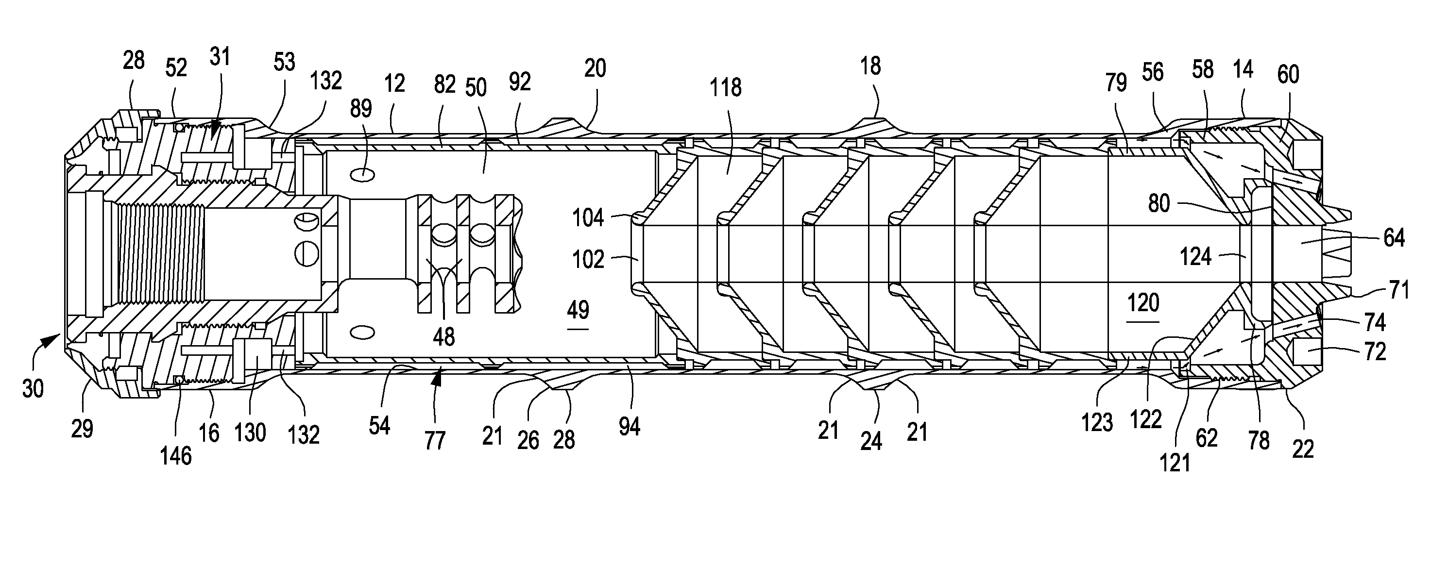
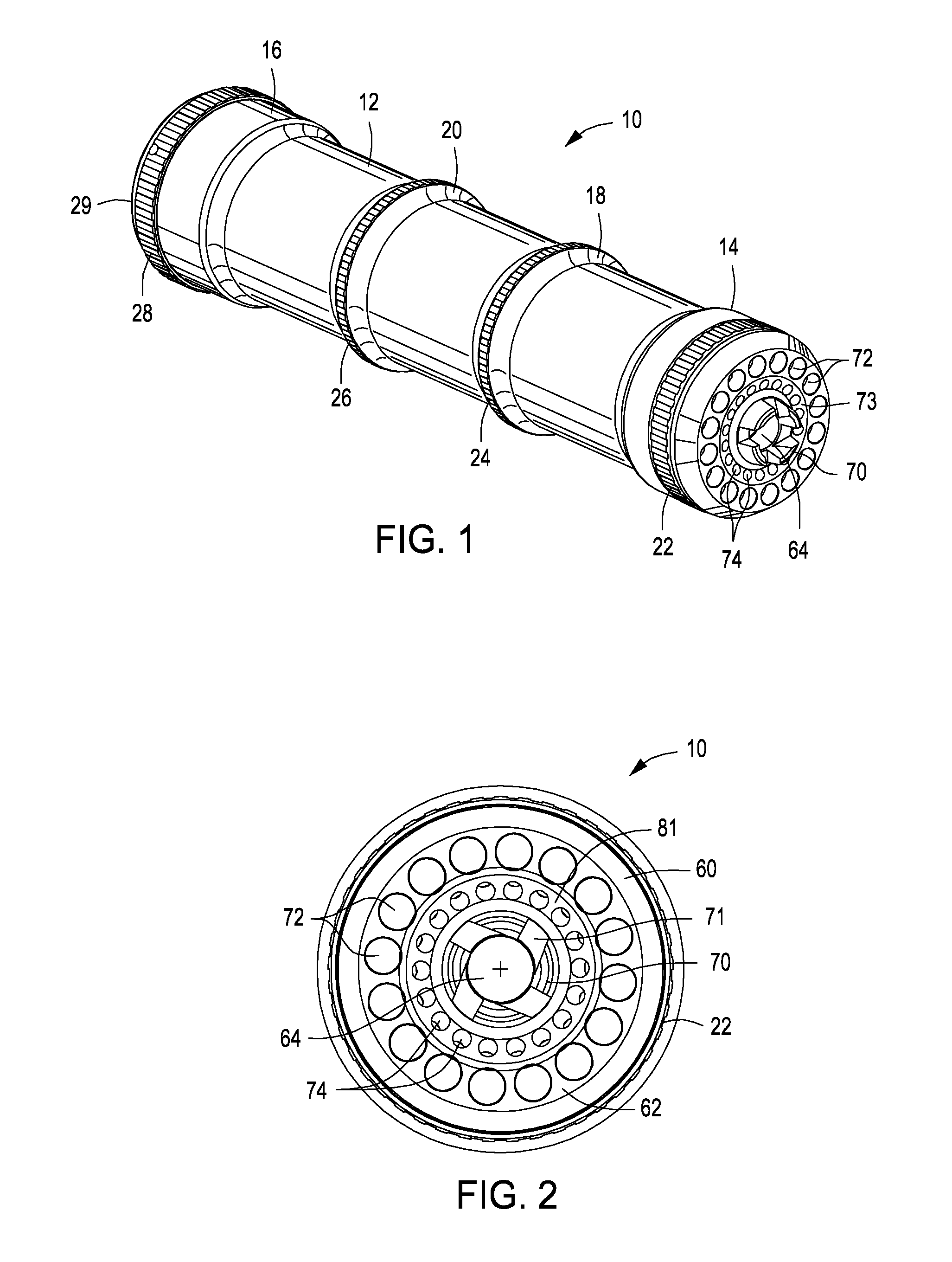
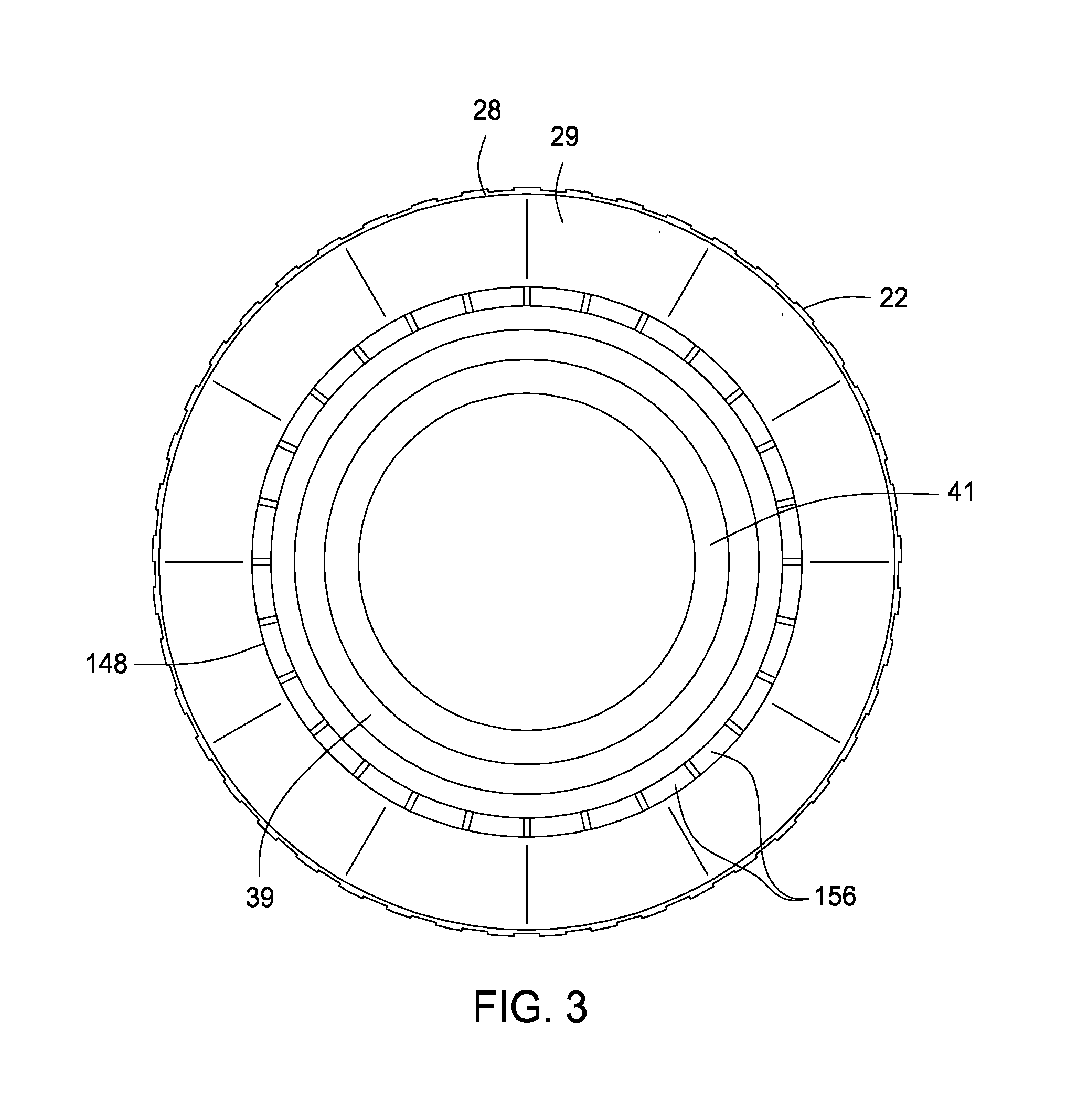
[0026]Referring now to the drawings and first to FIG. 1, a sound and flash suppressor device embodying the principles of the present invention is shown generally at 10 and incorporates an elongate tubular housing 12 having a defined length. The tubular housing 12 is strengthened at its forward and rear ends by generally cylindrical thickened enlarged housing wall sections 14 and 16 and is strengthened intermediate its extremities by annular external bosses 18 and 20 having curved side edges 21. Circular knurled regions 22, 24 and 26 are defined by the forward enlarged housing wall section and by the intermediate annular bosses 18 and 20. Another circular knurled section 28 is defined by a circular retainer cap 29 that is mounted to the rear end portion of the sound and flash suppressor assembly 10, the knurled sections being provided to facilitate secure manual grasping of the suppressor device when attaching it to or removing it from the barrel of a firearm,

[0027]As shown in detail...


PUM


Abstract

A firearm noise suppressor and flash hider device having a tubular housing having left hand threaded components. A suppressor mount securing and aligning the tubular housing relative to a firearm barrel. A number of propellant gas handling members within the housing define aligned projectile ports and baffle chambers to permit projectile movement and slow the progress of propellant gas as it traverses the internal chamber. These gas handling members define primary and secondary flow paths within the housing to divide the propellant gas discharge from the barrel and minimize gas pressure and volume of flow, resulting in lower propellant pressure, minimized noise and propellant flash. The primary and secondary flow paths each have separate discharge openings at the forward end of the suppressor.

Description

BACKGROUND OF THE INVENTION[0001]1. Field of the Invention[0002]The present invention is directed generally to sound suppressors that are designed for removable attachment to the threaded end of the barrel of a firearm, particularly a rifle. The present invention also concerns suppressors having the capability for suppressing the rather harsh sound of firearm discharge, but also substantially eliminating the rather bright flash that is generally projected from the bore of a firearm barrel when the firearm is discharged. More specifically, the present invention concerns a suppressor device that divides the propellant gas discharge of a firearm barrel into primary and secondary paths that have different discharge openings and serve to lower propellant gas pressure within the suppressor and minimize discharge sound and substantially eliminate propellant flash and minimize the potential for propellant gas blow-back toward the firearm user.[0003]2. Description of the Prior Art[0004]A sig...

Claims


Application Information

Patent Timeline
Patent Type & Authority Patents(United States)
IPC IPC(8): F41A21/30F41A21/34F41A21/28
CPCF41A21/30F41A21/34F41A21/28
Inventor LARUE, MARK C.
Owner LARUE MARK C
Why Eureka
Try Eureka