Light emitting device
a technology of light-emitting devices and light-emitting components, which is applied in the field of light-emitting devices, can solve the problems of increased number of components, high cost, and easy drop in production and supply of plants such as vegetables and fruits, and achieves the effects of brighter light, increased production efficiency, and adequate crystal growth
- Summary
- Abstract
- Description
- Claims
- Application Information
AI Technical Summary
Benefits of technology
Problems solved by technology
Method used
Image
Examples
first embodiment
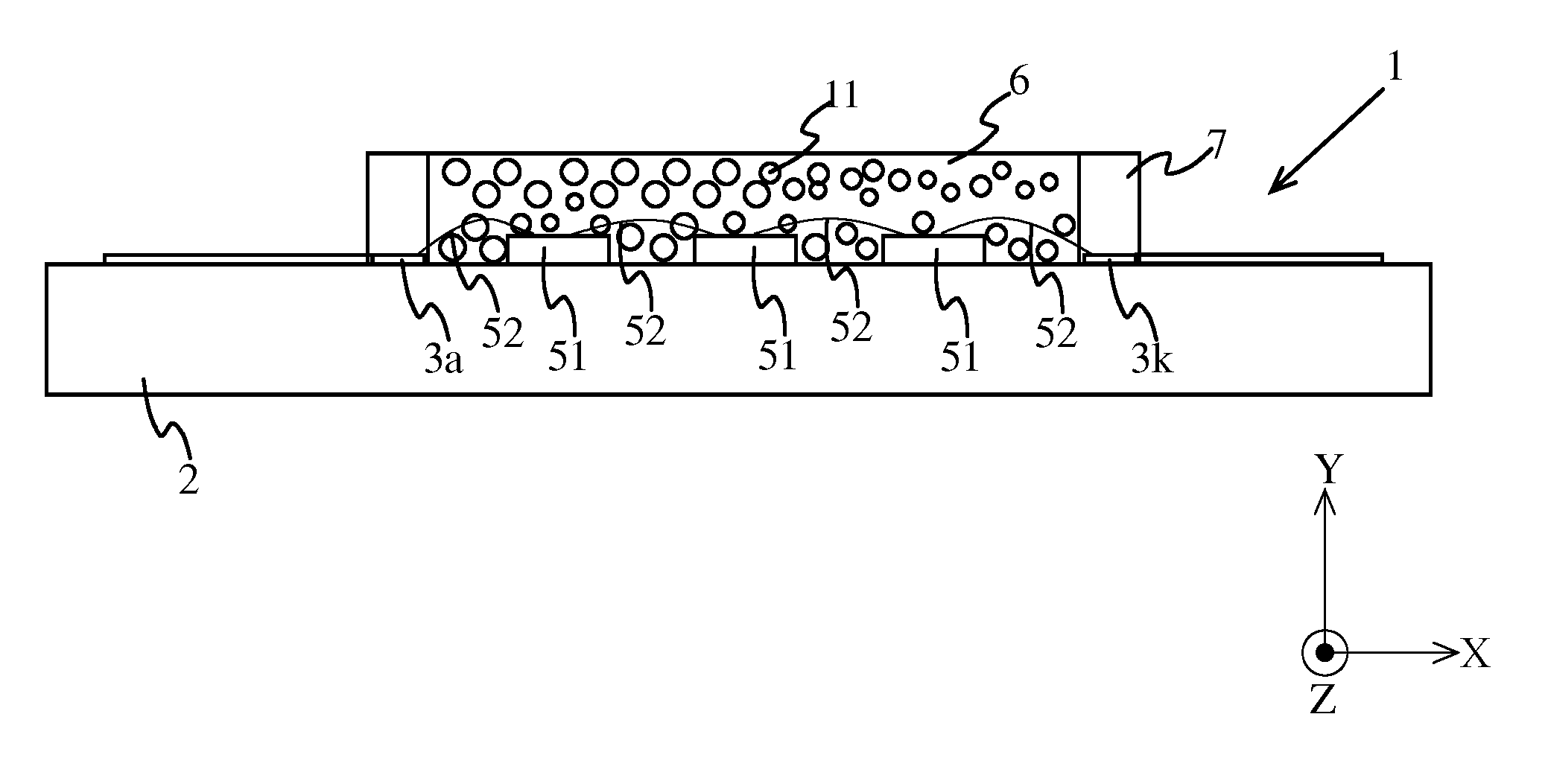
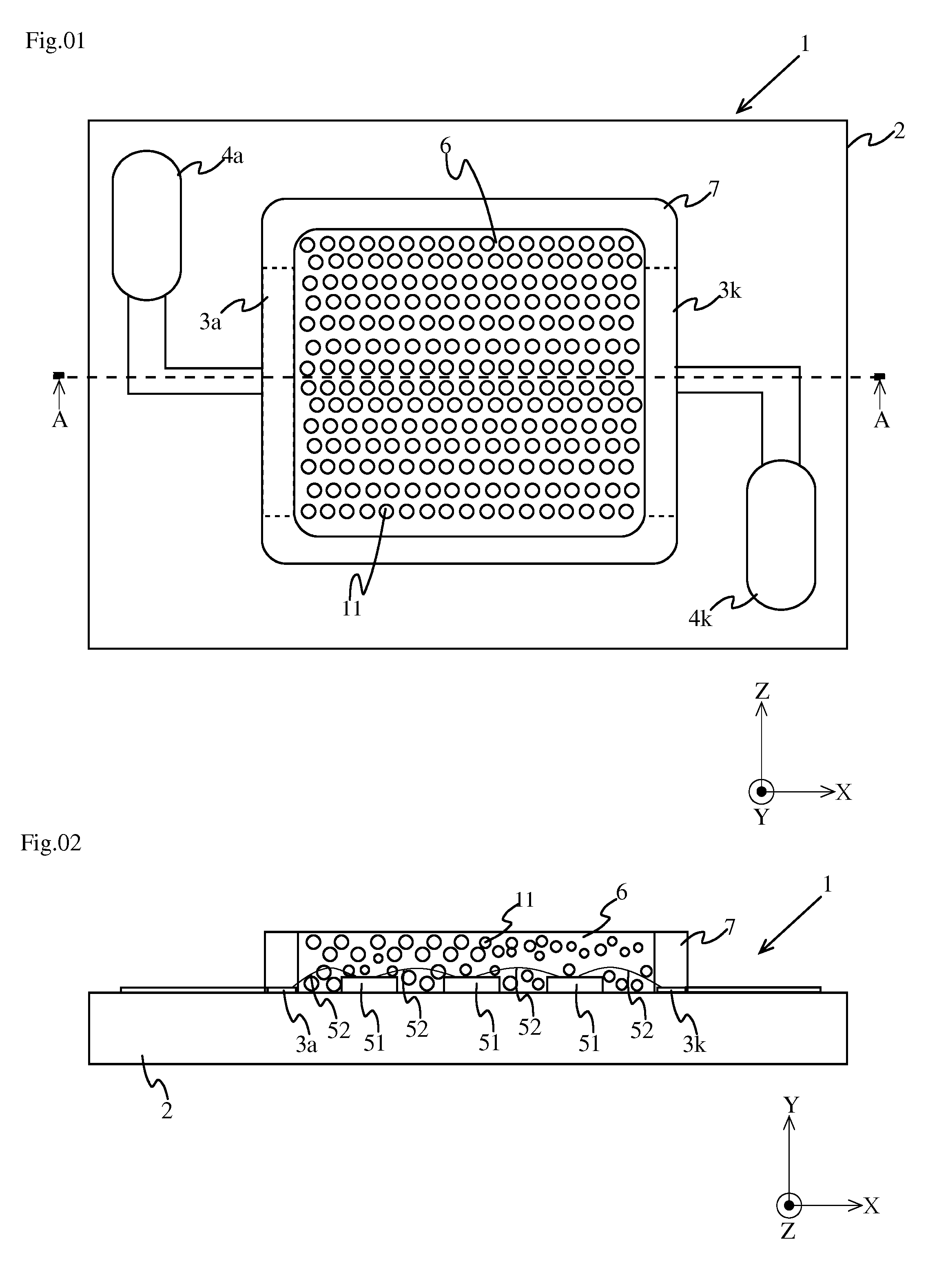
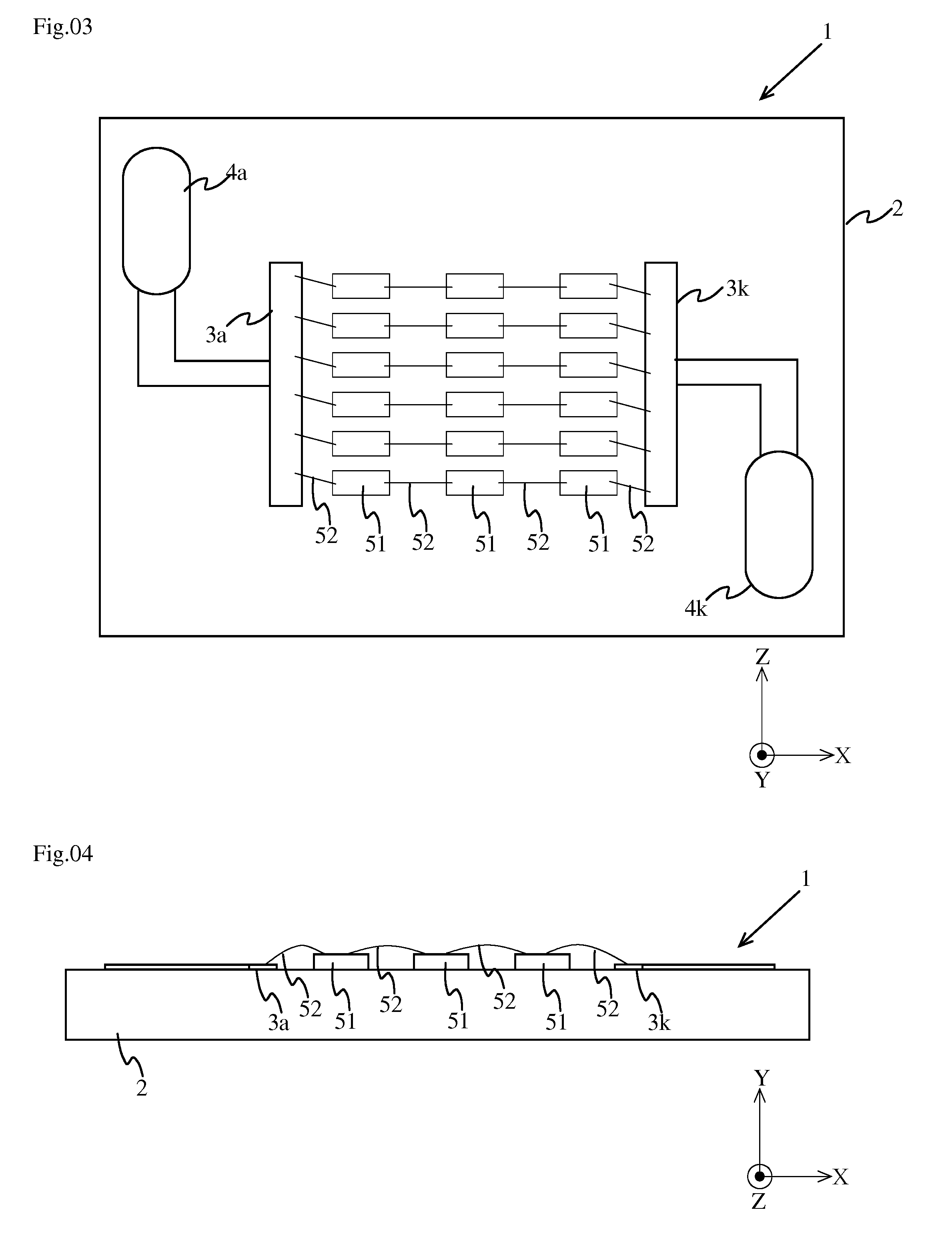
[0045]Prior to a description of a first embodiment of the present invention, a brief description will be given of the growth of plants. Light acts as a source of stimuli and a source of information in plants' sprouting, flowering, stalk growth, etc. In plants, photosynthesis takes place as a result of chlorophyll absorbing light. The absorption of light by chlorophyll peaks in two wavelength regions, the first being a wavelength range of 400 nm to 500 nm (more specifically, around 450 nm) and the second being a wavelength range of 600 nm to 700 nm (more specifically, around 660 nm).
[0046]Light in the first region (blue light) is necessary for proper morphogenesis of leaves etc., and light in the second region (red light) is necessary for photosynthesis. Moreover, in cases where plants are irradiated with mixed light, far-red light is considered necessary for internode growth and sprout formation. Phytochrome in plants absorbs different types of light by undergoing reversible photoco...
second embodiment
[0068]FIG. 5 is a top view of a light emitting device according to a second embodiment of the present invention. FIG. 6 is a side sectional view of the light emitting element shown in FIG. 5, taken on a YX section across line A-A. Here, the LED mounted on the substrate is similar to that in the first embodiment, and is therefore omitted from illustration. For such parts as find their counterparts in the first embodiment, no overlapping description will be repeated unless it is necessary.
[0069]The phosphor layer 6 is a resin layer which fills inside the resin frame 7 so as to cover the LED 5. The phosphor layer 6 emits light having a peak wavelength in a predetermined wavelength range by excitation with light (excitation light) emitted from the LED 5. The phosphor layer 6 is composed of a first phosphor layer 61 and a second phosphor layer 62. The first phosphor layer 61 is formed of sealing resin, which comprises silicone resin, containing a first phosphor 10 (indicated by triangula...
third embodiment
[0085]FIG. 7 is a top view showing a light emitting device according to a third embodiment of the present invention. FIG. 8 is a side sectional view of the light emitting device shown in FIG. 7, taken on an XY section across line B-B. FIG. 9 is a top view showing LEDs mounted on a substrate in the third embodiment. FIG. 10 is a schematic diagram showing a positional relationship between phosphor layers and LEDs. In FIG. 10, for an easy grasp of the positional relationship between phosphor layers and LEDs, triangular and circular symbols indicating the first and second phosphors 10 and 11, respectively, are omitted.
[0086]In the second embodiment described previously, the absorption of red light by the second phosphor layer 62 is reduced by stacking the first phosphor layer 61 over the second phosphor layer 62. In this embodiment, the absorption of red light by the second phosphor layer 62 is reduced without stacking the first and second phosphor layers together.
[0087]In this embodime...
PUM
| Property | Measurement | Unit |
|---|---|---|
| peak wavelength | aaaaa | aaaaa |
| peak wavelength | aaaaa | aaaaa |
| peak wavelength | aaaaa | aaaaa |
Abstract
Description
Claims
Application Information
 - R&D
- Intellectual Property
- Life Sciences
- Materials
- Tech Scout
- Unparalleled Data Quality
- Higher Quality Content
- 60% Fewer Hallucinations
Browse by: Latest US Patents, China's latest patents, Technical Efficacy Thesaurus, Application Domain, Technology Topic, Popular Technical Reports.
© 2025 PatSnap. All rights reserved.Legal|Privacy policy|Modern Slavery Act Transparency Statement|Sitemap|About US| Contact US: help@patsnap.com


