Surgical tool arrangement

a technology of surgical tools and tools, applied in the field of surgical tool arrangement, can solve the problems of inconsistent performance, significant increase in the overall size of the device, inconsistent energy delivery,

Active Publication Date: 2016-11-29
STRYKER CORP
View PDF88 Cites 807 Cited by
  • Summary
  • Abstract
  • Description
  • Claims
  • Application Information

AI Technical Summary

Benefits of technology

[0010]Because the instant invention does not utilize the moving cutting element as an energy delivering electrode, the energy delivery at the cutting interface is consistent, thus resulting in more consistent tool performance. Further, since the moving cutting element is not utilized as an active electrode, there is no requirement to electrically isolate the mechanical cutting element from the outer housing element.
[0011]Further, the instant invention incorporates an electrical coupling between the handpiece and the integrated tool, which coupling provides electrical energy to the electrode arrangement of the integrated tool via the handpiece, thereby eliminating the need for a separate power cable.

Problems solved by technology

One disadvantage of the above tools is that, since the rotating blade tip is utilized as the active, energy-delivering electrode, the surface area of the active electrode defined by the rotating blade tip varies, which can create inconsistent energy delivery and thus inconsistent performance.
This adapter device, however, requires that an additional housing (i.e. the sheath) be placed over the existing housing of the cutting device, which significantly increases the overall size of the device, which in turn requires that a larger entry port be made in the patient.

Method used


Image

  • Surgical tool arrangement
  • Surgical tool arrangement
  • Surgical tool arrangement

Examples


third embodiment

[0076]FIGS. 10 and 11 illustrate a combined electrosurgical tool and cutting instrument 110 which may be utilized with handpiece 11. In this embodiment, the instrument 110 includes an inner housing tube 111 constructed of metal, for example stainless steel. An outer housing tube 112 is disposed over the inner tube 111 and is non-movable relative thereto. Outer tube 112 is constructed of rigid plastic, and includes a conductive wire mesh or coil 113 embedded therein. The respective tubes 111 and 112 are then cut as described above to define a window 114 at the distal end of instrument 110, as in the above embodiments. The cutting process exposes a ring-shaped area 115 of inner tube 111, inwardly of the edge of outer tube 112. Area 115 defines a cutting edge 116 which cooperates with the cutting head 71 of cutting element 15 to sever tissue. After cutting of the instrument 110 to define window 114, the plastic of outer tube 112 is removed around portions of the wire mesh 113 to define...

first embodiment

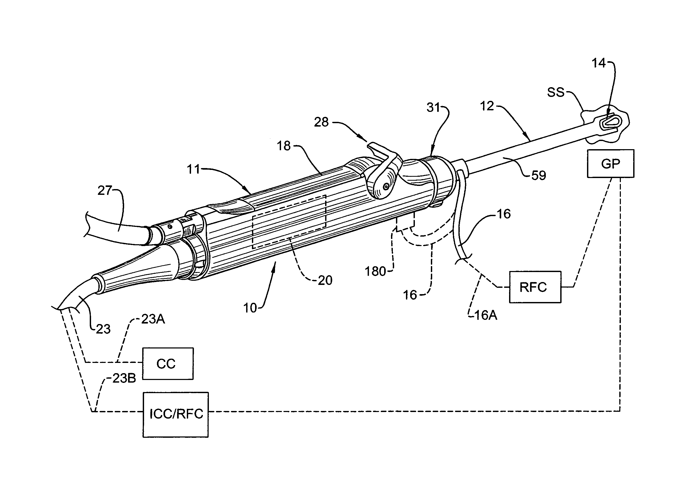
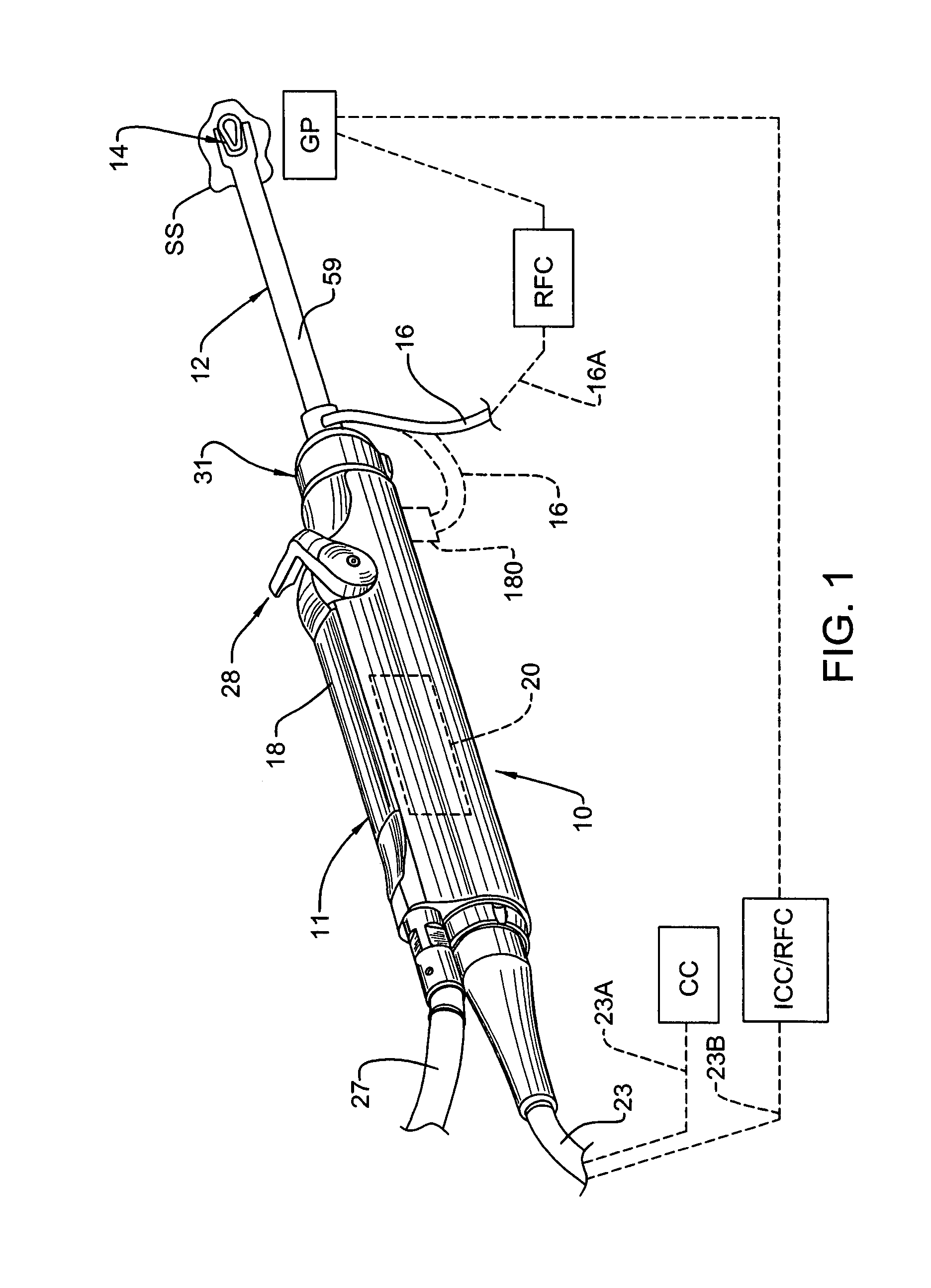
[0077]The first three embodiments of the combined electrosurgical tool and cutting instrument are disclosed herein as being utilized as monopolar instruments in conjunction with a patient grounding pad (GP). However it may be possible or desirable to utilize some of these instruments as bipolar instruments. For example, and with respect to FIGS. 5-7, the housing tube 80 and its exposed ring-like portion 82A can be used as the return path for the electrical current delivered to the surgical site (SS) via electrode arrangement 14. In this instance, the insulating layer 81 can be removed from (or not initially applied to) an area located on the proximal end of housing tube 80 inside head 44 of hub 40, and then electrically connected to cable 16, wherein cable 16 would be configured to both deliver electrical current to electrode arrangement 14 from RF control (RFC) and return current from housing tube 80 to RF control (RFC).

[0078]With respect to the third embodiment illustrated in FIGS...

fourth embodiment

[0079]FIGS. 12 and 13 illustrate a combined electrosurgical and cutting instrument 120 which may be utilized with handpiece 11. In this embodiment, instrument 120 is a multi-layer component. More specifically, instrument 120 includes an innermost housing tube 121 of a conductive material, such as stainless steel. The outer surface of tube 121 is coated with an insulating layer 123. The insulating layer 123 is covered with a conductive layer 124, such as copper, and the conductive layer 124 is covered with a further insulating layer 125. In this embodiment as in the prior embodiments, the instrument 120 is cut at its distal end to define a window 127, which cutting process results in the formation of an annular electrode 129 defined by the exposed distal end of the conductive layer 124. The exposed distal end of inner housing tube 121 defines a ring-like area 130, the innermost edge of which defines a cutting edge 131 which cooperates with cutting head 71 of cutting element 15 to sev...


PUM


Abstract

A surgical tool arrangement including a powered handpiece which cooperates with a combined electrosurgical and mechanical cutting instrument. The electrosurgical and mechanical cutting instrument includes an outer static housing element which defines an electrode for delivering electrical energy to the surgical site, and a cutting element disposed within the outer housing and movable relative thereto for manipulating patient tissue. The electrosurgical and mechanical cutting instrument is an integral component attachable to the surgical tool to provide multiple functions in a single instrument, such as cauterization, ablation and mechanical cutting, without the need for attachment of additional housing structures or other adapters. The tool arrangement also includes a universal handpiece which is capable of accepting and operating a number of different surgical instruments, each having one or multiple functions.

Description

CROSS-REFERENCE TO RELATED APPLICATIONS[0001]This is the National Stage of International Application No. PCT / US2006 / 009802, filed Mar. 17, 2006, which claims the benefit of U.S. Provisional Application No. 60 / 662,735, filed Mar. 17, 2005.FIELD OF THE INVENTION[0002]This invention is generally related to a surgical tool arrangement, and specifically to an arrangement which is capable of carrying out mechanical cutting, electrocauterization and ablation of tissue. The invention also relates to a universal surgical handpiece which is able to operate a number of different surgical tools or instruments which detachably connect to the handpiece.BACKGROUND OF THE INVENTION[0003]Surgical tools designed for mechanical cutting of tissue have been used for a number of years. These types of tools typically include a powered handpiece and a cutting tool which is secured in the distal end of the handpiece. The tool has an inner drive member including a hub drivingly engaged with an output shaft a...

Claims


Application Information

Patent Timeline
Patent Type & Authority Patents(United States)
IPC IPC(8): A61B18/14A61B17/32A61B17/00A61B18/00
CPCA61B18/1485A61B17/32002A61B17/32A61B18/14A61B2017/0046A61B2018/00178
Inventor DEUTMEYER, KURT M.ROBISON, BRADEN M.HAMEL, ANDREW J.HILLDOERFER, MICHAEL G.
Owner STRYKER CORP
Why Eureka
Try Eureka