Energy absorber with sidewall stabilizer ribs

a technology of stabilizer ribs and energy absorbers, which is applied in the direction of bumpers, vehicle components, vehicular safety arrangements, etc., can solve the problems of conflicting design requirements, affecting the moldability of parts, and adding to the cost of dies and mold cycle times and maintenance, so as to prevent premature collapse

Active Publication Date: 2011-09-13
SHAPE CORP
View PDF76 Cites 30 Cited by
  • Summary
  • Abstract
  • Description
  • Claims
  • Application Information

AI Technical Summary

Benefits of technology

[0006]In one aspect of the present invention, a bumper system for vehicles includes an elongated reinforcement beam adapted for mounting to a vehicle frame and an energy absorber abutting a front surface of the reinforcement beam. The energy absorber includes at least one hollow crush lobe configured to crush and absorb energy upon a vehicle crash, the at least one crush lobe including interconnected top, bottom, end and front walls. At least one opposing pair of the walls is elongated parallel a length of the beam to define enlarged areas that are generally unsupported, but the one pair of walls further include external ribs extending perpendicular to the length for stabilizing the enlarged areas, such as by adding stiffeners to the walls to prevent premature collapse.
[0010]The present invention focuses on a discovery that stability of enlarged walls in crush lobes of energy absorbers can be greatly improved by external ribs. The external ribs are easily placed in molds and can be readily modified in the mold tooling, thus leading to improved / shorter mold lead times, improved and simplified molds, etc. Additionally, the ribs can be quickly and easily modified in prototype samples during the development phase of a program. Further, the external ribs can be sometimes be used for additional functions, such as to support fascia on the bumper system. The ribs can also be used to tune performance by having a varying height or width or location. This is highly advantageous because it allows the walls of the lobe to have a uniform thickness which provides a better molding condition. Furthermore, when the external ribs are placed at consistent intervals or at critical areas, the performance of the energy absorber is more consistent across its length, which is highly desirable for some impacts such as pedestrian impacts. Similarly, the frequency of the ribs can be decreased towards the ends of the lobe to normalize the stiffness since the end wall makes the lobe naturally stiffer at that location.

Problems solved by technology

However, complexity of the energy absorber adversely affects the lead times required by mold shops for providing the molds, and further adversely affects moldability of the parts, such as by adding to die cost and mold cycle times and maintenance.
Complexity can come from many things, including the shape, size, and / or number of crush boxes required.
This results in conflicting design requirements.
On the one hand, energy absorbers can be designed to have smaller crush boxes, but the molds (and the molding process) become more complex due to an increased number of crush boxes required to cover the front surface area of the bumper reinforcement.
Further, the energy absorbers become much heavier due to additional material in the walls of the “additional” crush boxes, and mold cycle times increase due to the additional material.
Also, molds can become more complex due to undulations and other structure placed in the walls.
Energy absorbers are easier to mold (and lighter in weight) when they have larger crush boxes, but large unsupported areas in the walls of the crush boxes tend to be unstable, leading to premature collapse during impact (i.e., inconsistency) and / or poor energy absorption.
Yet, tooling must often be started early in the program.
“Tuning” of bumper systems can be difficult and time consuming in and of itself, particularly when the molds must be sent offsite in order to machine in thicker walls or new wall shapes.

Method used


Image

  • Energy absorber with sidewall stabilizer ribs
  • Energy absorber with sidewall stabilizer ribs
  • Energy absorber with sidewall stabilizer ribs

Examples


Embodiment Construction

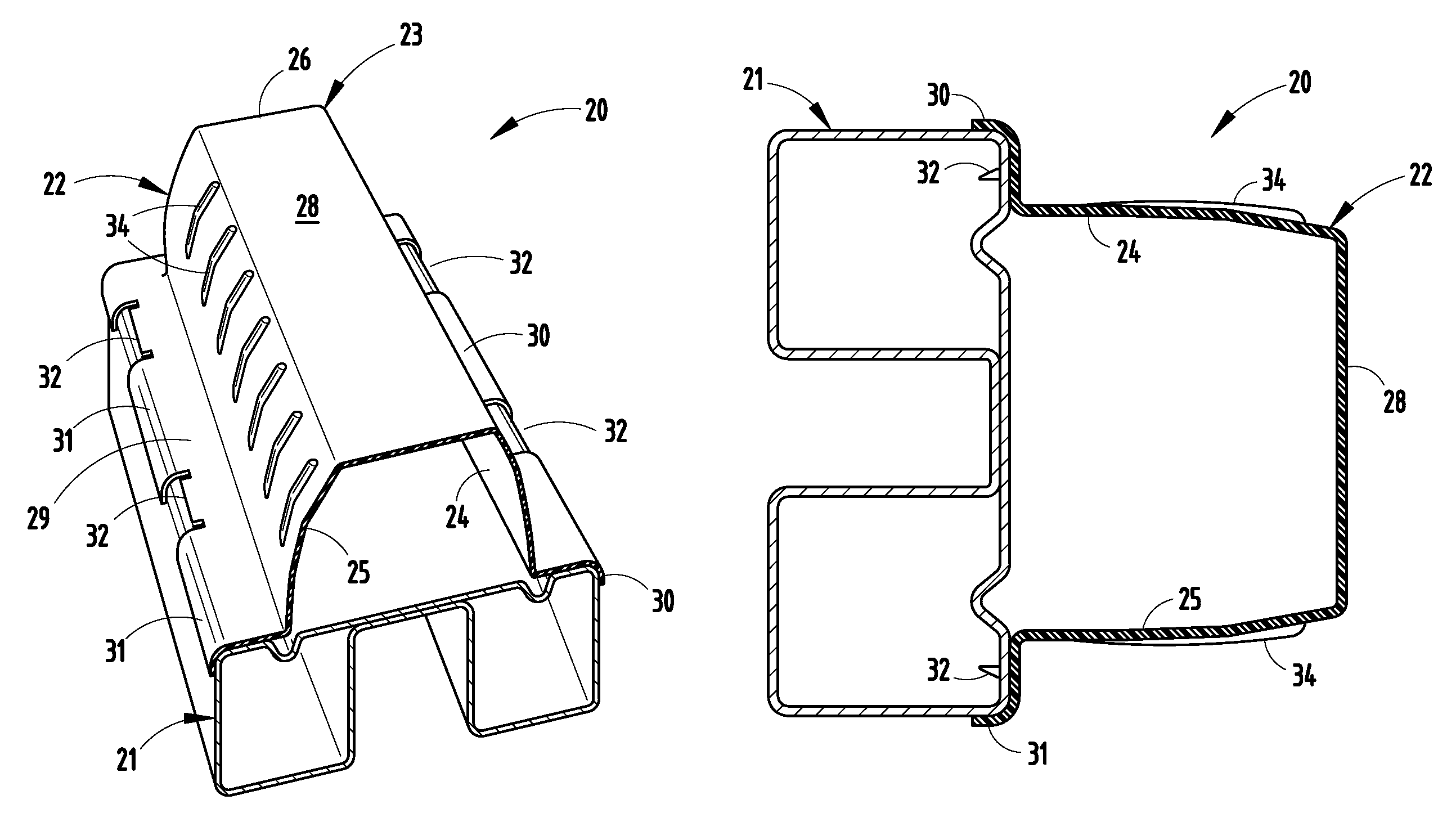
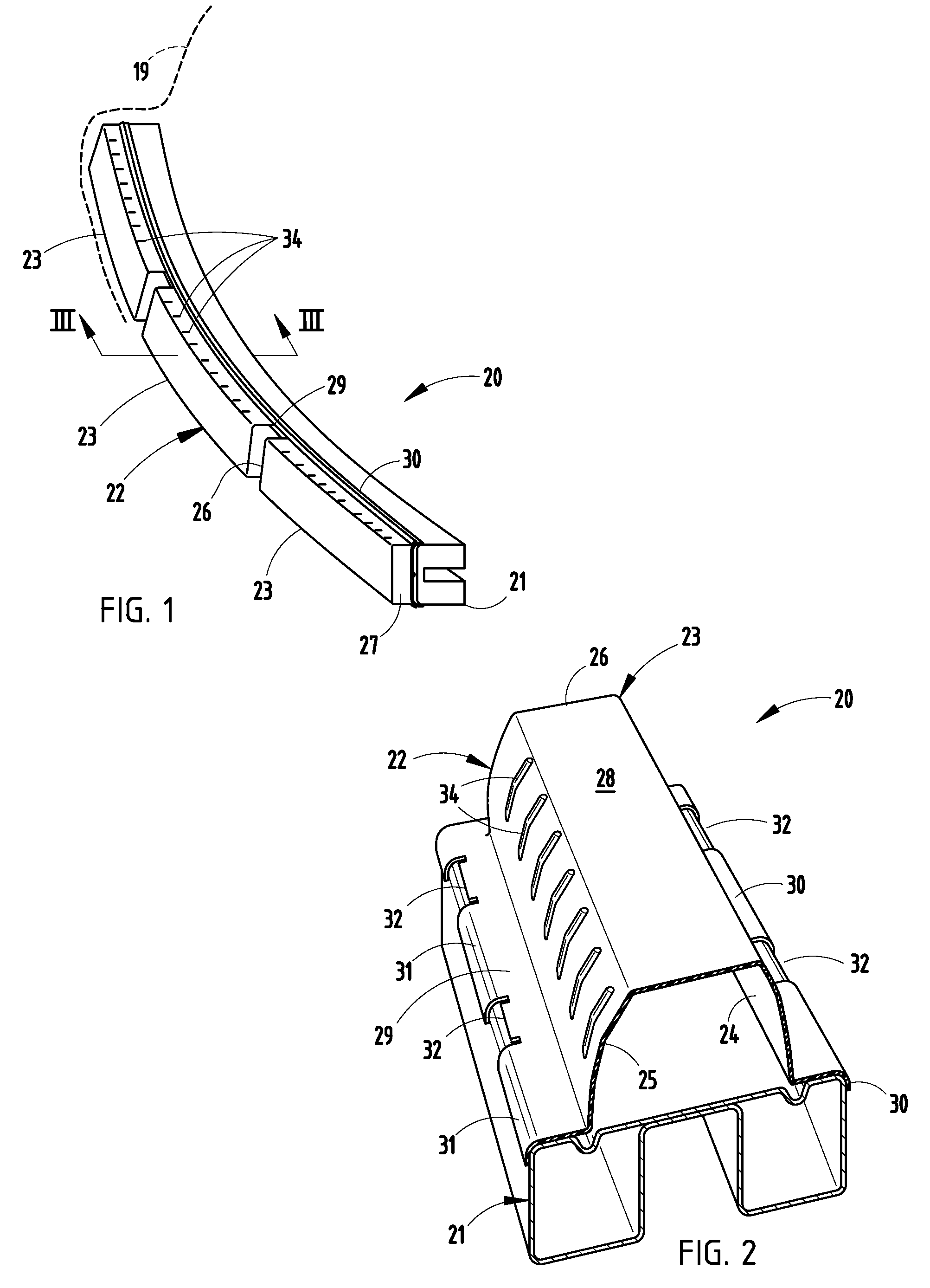
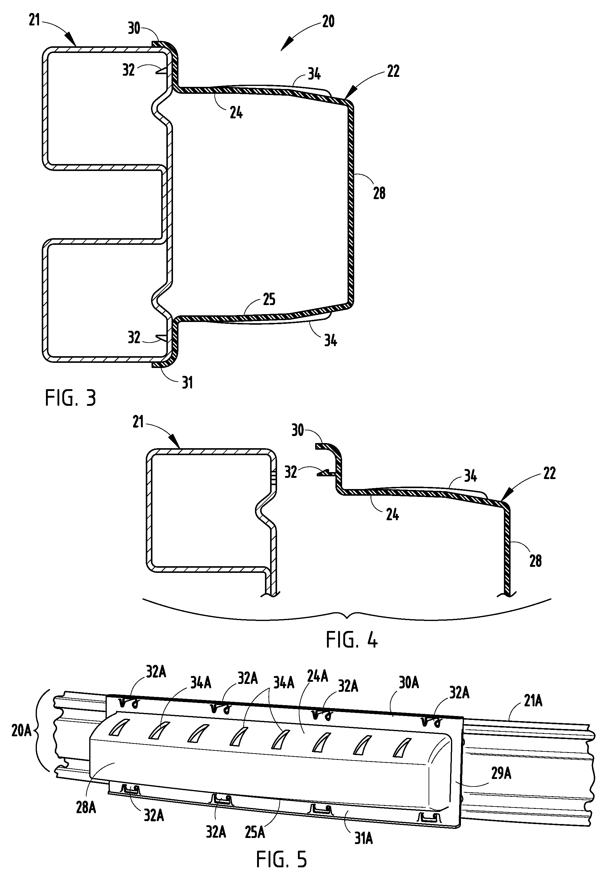
[0021]A vehicle bumper system 20 (FIG. 1) includes an elongated steel B-shaped reinforcement beam 21 with ends adapted / configured for mounting to a vehicle frame, and further includes a polymeric energy absorber 22 abutting or parallel to a front surface of the reinforcement beam 21 and positioned under (and supporting) the vehicle RIM fascia 19. (It is contemplated that the energy absorber 22 could be connected to and supported by the fascia 19 and / or to the beam 20.) The energy absorber 22 includes three (or more or less) longitudinally-elongated hollow crush lobes 23 configured to crush and absorb energy upon a vehicle crash. Specifically, the crush lobes 23 each include interconnected wall structure forming a box shape (often called a “crush box”), including a top side wall 24, a bottom side wall 25, end walls 26-27 and a front wall 28. The energy absorber 22 further includes a frame comprising a rear wall 29 and top and bottom flanges 30-31 for retaining the crush lobes 23 to t...


PUM


Abstract

A vehicle bumper system includes an elongated reinforcement beam for mounting to a vehicle frame and an energy absorber abutting a front surface of the reinforcement beam. The energy absorber includes longitudinally-elongated hollow crush lobes configured to crush and absorb energy upon a vehicle crash, the crush lobes including interconnected top, bottom, side and front walls. At least one opposing pair of the walls, such as the top and bottom walls, are elongated parallel a length of the beam to define enlarged areas that are generally unsupported, but the one pair of walls further include a plurality of spaced external ribs extending perpendicular to the length for stabilizing the enlarged areas.

Description

[0001]This application claims benefit under 35 U.S.C. §119(e) of provisional application Ser. No. 61 / 028,704, filed Feb. 14, 2008, entitled ENERGY ABSORBER WITH EXTERNAL STABILIZER RIBS, and further claims benefit of provisional application Ser. No. 61 / 028,700, filed Feb. 14, 2008, entitled ENERGY ABSORBER WITH INTERNALLY SUPPORTED CRUSH BOXES, both of which are co-assigned and incorporated herein in their entirety.BACKGROUND[0002]The present invention relates to bumper systems using energy absorbers, and more particularly to automotive polymeric energy absorbers such as for a vehicle front or rear bumper. However, a scope of the present invention is not believed to be limited to only bumper energy absorbers and / or bumper systems.[0003]Many automotive bumper systems include metal reinforcement beams and polymeric energy absorbers tuned for very specific energy absorption profiles, including “softer” initial impact strokes for pedestrian safety and “harder” deep-stroke impacts such a...

Claims


Application Information

Patent Timeline
Patent Type & Authority Patents(United States)
IPC IPC(8): B60R19/04
CPCB60R19/18B60R2019/186B60R2019/1893
Inventor RALSTON, DANIEL D.HOLDREN, KEVIN E.BASTIEN, KENNETH R.GORMAN, DAVIDKULKARNI, AMIT
Owner SHAPE CORP
Why Eureka
Try Eureka