Surface cleaning appliance

a technology for cleaning appliances and surfaces, applied in the direction of washing machines, cleaning processes and apparatuses, applications, etc., can solve the problems of unaffected motor performance and voltage drop across electrical components, and achieve the effect of simple and cheap controllers, reduced torque-speed curves of motors operating at different supply voltages, and reduced power consumption

Active Publication Date: 2014-12-18
DYSON TECH LTD
View PDF6 Cites 27 Cited by
  • Summary
  • Abstract
  • Description
  • Claims
  • Application Information

AI Technical Summary

Benefits of technology

[0008]When the switch is closed, the voltage drop across the series-connected components is proportional to the motor current. However, when the switch is open, the voltage drop across the series-connected components is zero. The voltage drop, when averaged over each cycle of the PWM signal, therefore depends on the current and on the duty cycle of the PWM signal, which in turns depends on the supply voltage. Accordingly, when adjusting the duty cycle in response to changes in the current, the controller may adjust the duty cycle by an amount that depends not only on the change in the motor current but also on the magnitude of the supply voltage. That is to say that, in response to a given change in the motor current, the controller may adjust the duty cycle by an amount that depends on the magnitude of the supply voltage. More particularly, the controller may adjust the duty cycle by a larger amount in response to a lower supply voltage. As a result, differences in the torque-speed curve of the motor when operating at different supply voltages may be reduced. In particular, by ensuring that the input voltage to the motor is constant, the same torque-speed curve may be achieved at different supply voltages.
[0009]The controller may store a voltage lookup table and a current lookup table, and the controller may index the voltage lookup table using the measured supply voltage to select a first value, and the controller may index the current lookup table using the measured motor current to select a second value

Problems solved by technology

Owing to Ohmic losses, there is a voltage drop across electrical components connected in series with

Method used


Image

  • Surface cleaning appliance
  • Surface cleaning appliance
  • Surface cleaning appliance

Examples


Embodiment Construction

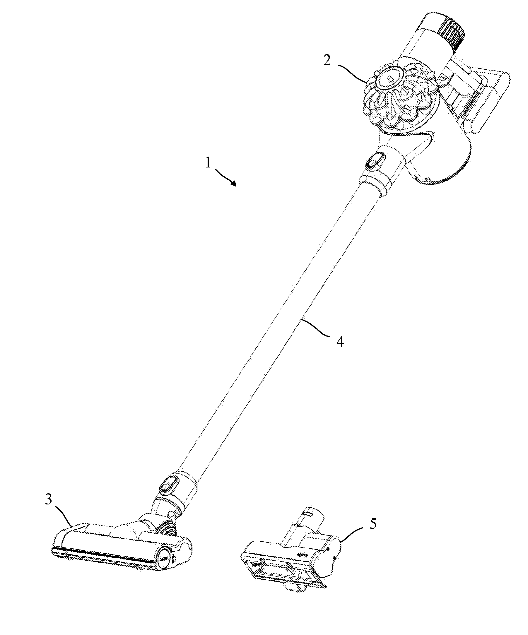
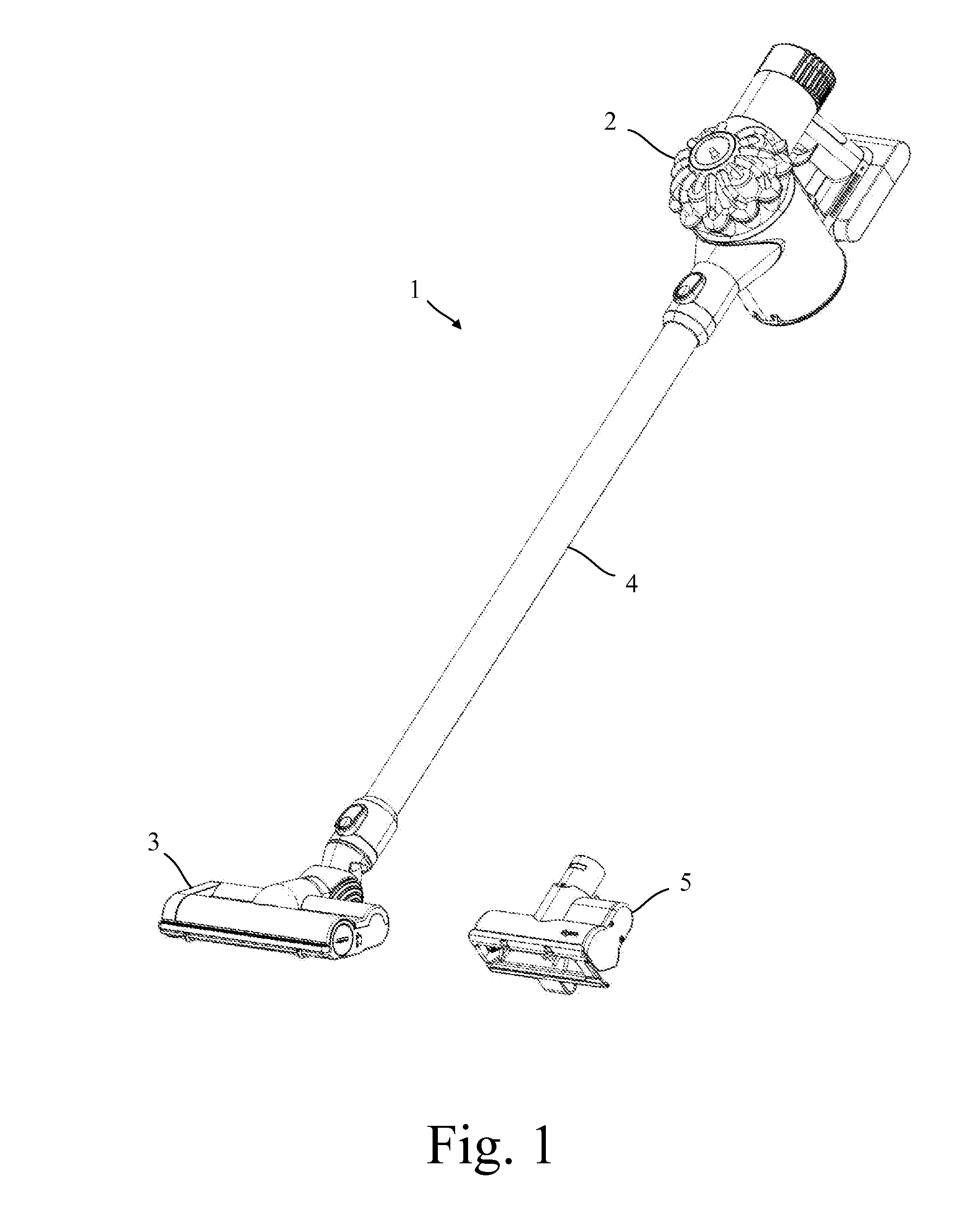
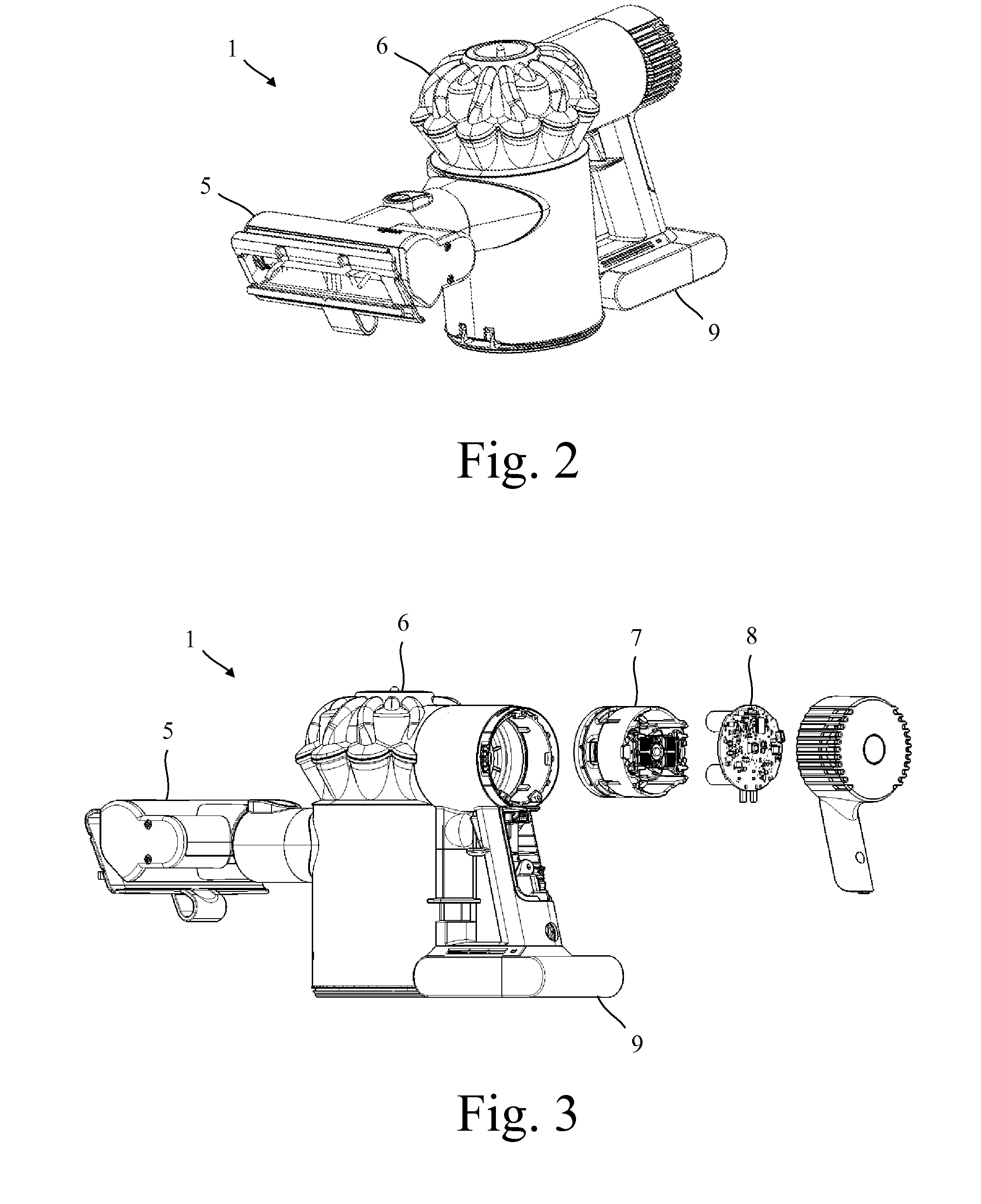
[0027]The vacuum cleaner 1 of FIGS. 1 to 6 comprises a main body 2 to which a cleaner head 3 is attached by means of an elongate tube 4. The main body 2 comprises a dirt separator 6, a suction source 7, a circuit assembly 8 and a battery pack 9. During use, dirt-laden air is drawn in through the cleaner head 3 and carried to the dirt separator via the tube 4. Dirt is then separated from the air and retained by the dirt separator 6. The cleansed air is then drawn through the suction source 7 and exhausted from the cleaner 1.

[0028]The cleaner head 3 and the tube 4 are detachable from the main body 2. Moreover, the vacuum cleaner 1 comprises a second cleaner head 5 that may be attached directly to the main body 2. As a result, the vacuum cleaner 1 may be used as an upright or stick cleaner (i.e. with the first cleaner head 3 and tube 4 attached to the main body 2 as shown in FIG. 1) or as a handheld cleaner (i.e. with the second cleaner head 5 attached directly to the main body 2 as sh...


PUM


Abstract

A surface cleaning appliance having a cleaner head that includes an agitator and a motor for driving the agitator. The appliance includes a switch coupling the motor to a supply voltage, a voltage sensor for measuring the magnitude of the supply voltage, a current sensor for measuring the magnitude of current through the motor, and a controller configured to output a PWM signal for controlling the switch. The controller then adjusts the duty cycle of the PWM signal in response to changes in the supply voltage and in response to changes in the current through the motor.

Description

REFERENCE TO RELATED APPLICATION[0001]This application claims priority of United Kingdom Application No. 1310571.3, filed Jun. 13, 2013, the entire contents of which are incorporated herein by reference.FIELD OF THE INVENTION[0002]The present invention relates to a surface cleaning appliance.BACKGROUND OF THE INVENTION[0003]A surface cleaning appliance, such as a vacuum cleaner, may comprise a cleaner head having an agitator driven by a motor. Changes in the supply voltage used to power the motor are likely to influence the performance of the motor. As a result, the cleaning performance of the appliance may be inconsistent.SUMMARY OF THE INVENTION[0004]The present invention provides a surface cleaning appliance comprising a cleaner head comprising an agitator and a motor for driving the agitator, a switch coupling the motor to a supply voltage, a voltage sensor for measuring the magnitude of the supply voltage, a current sensor for measuring the magnitude of current through the moto...

Claims


Application Information

Patent Timeline
IPC IPC(8): A47L11/40A47L9/28
CPCA47L11/4011A47L11/4069A47L9/2847A47L9/2831A47L11/4008A47L9/2857A47L9/0411
Inventor ZHENG, LIBOZHOU, YONGJICHISHOLM, JAMES DOUGLASHAWKER, DAVID JOHN
Owner DYSON TECH LTD
Why Eureka
Try Eureka