Signaling system

Inactive Publication Date: 2006-11-16
VAISH HIMANGSHU RAI
View PDF19 Cites 25 Cited by
  • Summary
  • Abstract
  • Description
  • Claims
  • Application Information

AI Technical Summary

Benefits of technology

[0020] Above and other aspects of the invention together with one another or individually or in combination of further aspects, achi

Problems solved by technology

However existing LED based systems have certain limitations with respect to the heating of power supply, alarming systems and illumination of the LEDs, failure and reliability.
In this type of system when one or more LEDs fail the detection of failure is not foolproof because of the piece-to-piece variations in electrical characteristics of the ECR, which is con

Method used


Image

  • Signaling system
  • Signaling system
  • Signaling system

Examples


Example

DETAILED DESCRIPTION OF DRAWINGS

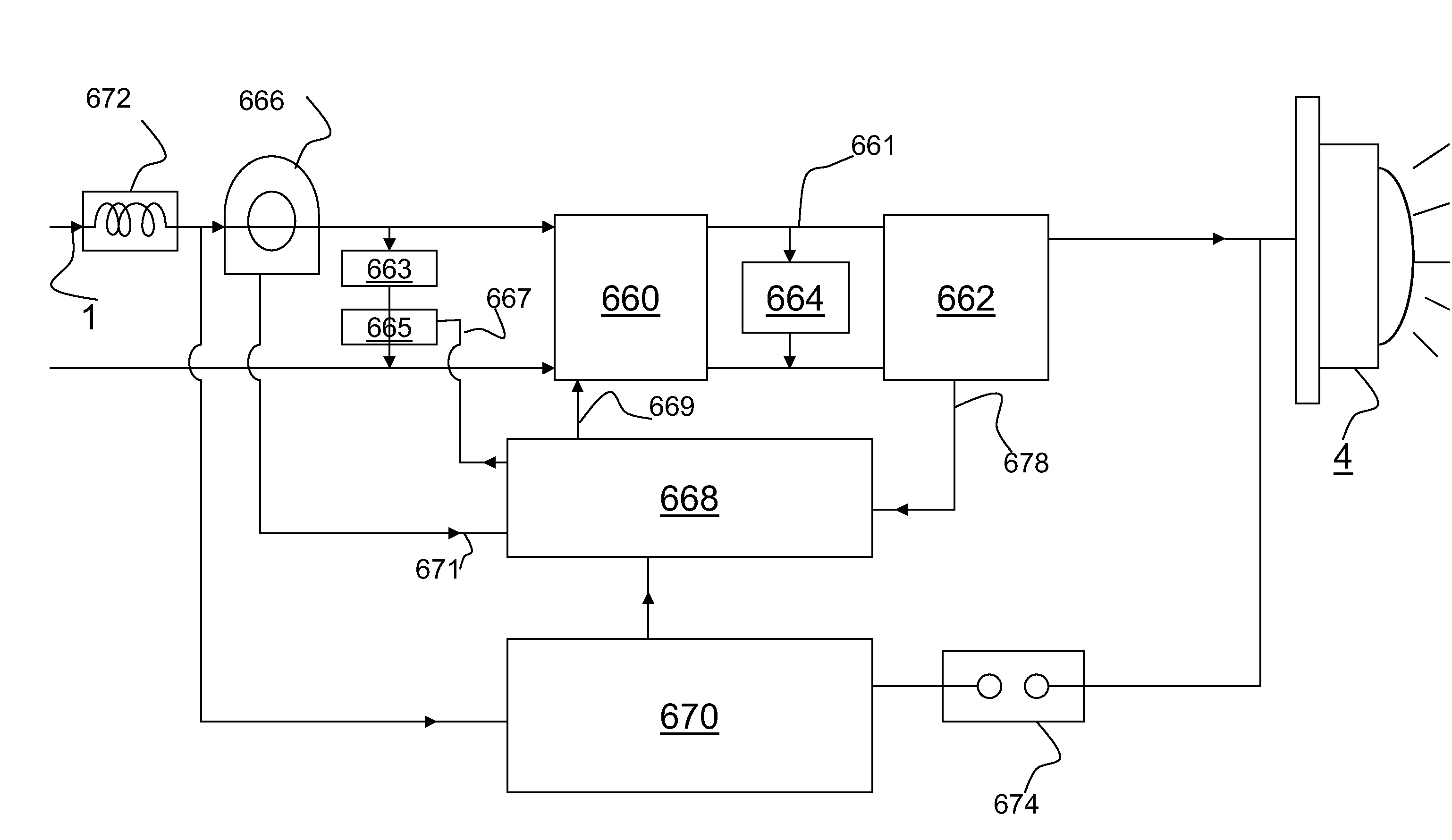
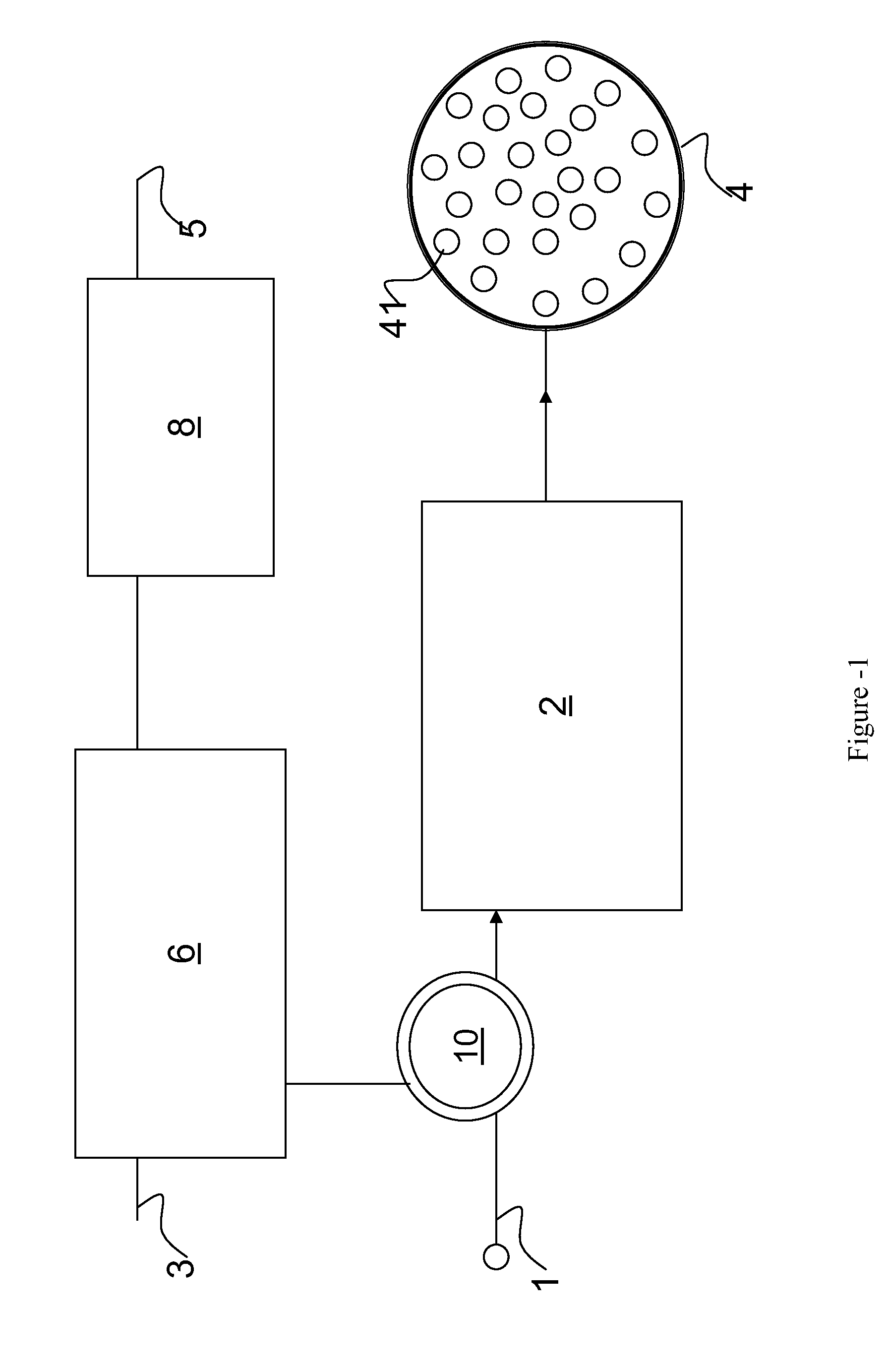
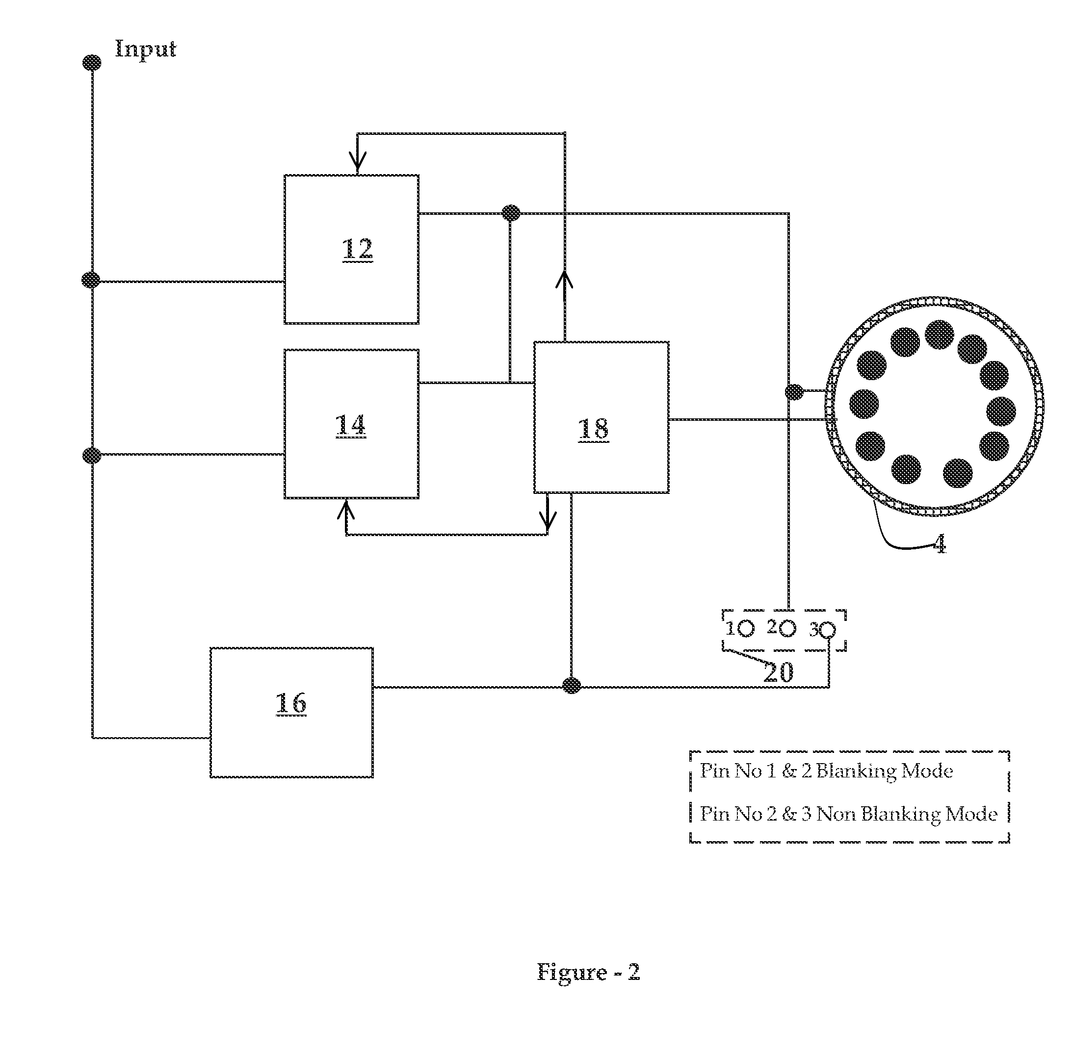
[0027] In FIG. 1, a signaling system is shown that comprises a power supply line 1 coupled to an aspect 4 through a current regulator 2. The aspect 4 comprises a plurality of LEDs 41. The LEDs 41 may be connected in parallel and / or in series or any combination thereof. The current regulator 2 provides a DC voltage to the aspect 4. The current regulator 2 regulates the current through the supply line and maintains it at a substantially constant value irrespective of the variation of the input voltage. The current regulator 2 also maintains the power factor substantially close to unity. More details in different embodiments of the current regulator are described in FIG. 2 and FIG. 3. Further the aspect 4, is coupled to an alarming system 6 through a current sensing coil 10. The sensing coil 10 is placed around the supply line 1 for sensing the current through the supply line 1. The sensing coil 10 is connected to alarming system 6. The coil 10 communic...


PUM


Abstract

A signaling system is presented. The signaling system comprises a power supply line coupled to an aspect through a current regulator. The aspect has a plurality of light sources. The current regulator is configured for maintaining substantially unity power factor and for maintaining substantially constant current through the supply line during normal operation of the system. The regulator is further configured for detecting a complete/partial failure of the aspect and communicating an indication indicative of the failure over the supply line by maintaining a significantly different current level through the supply line as against the normal constant current level. A distantly located alarming system is connected to detect partial/full failure of aspect and current regulator by variation in the current flowing through the supply line as against the constant current.

Description

FIELD OF THE INVENTION [0001] The present invention relates to a signaling system, and particularly to a railway signaling system. BACKGROUND [0002] Movement of trains is controlled by many factors such as, track availability, scheduled arrival and / or departure time. Railway administration processes various inputs and finally conveys its decision to the train driver through Red, Yellow, Green and some times white lights. [0003] Modern signaling systems use Light Emitting Diodes (LED). However existing LED based systems have certain limitations with respect to the heating of power supply, alarming systems and illumination of the LEDs, failure and reliability. [0004] Existing LED based signaling are normally using a plurality of serially connected LEDs, with linear power supplies and resistive loads for activating Electric Current Relay (ECR) also known as Lamp Proving Relay. In this type of system when one or more LEDs fail the detection of failure is not foolproof because of the pie...

Claims


Application Information

Patent Timeline
IPC IPC(8): G05D11/00
CPCB61L2207/02B61L5/1881H05B45/385H05B45/3725H05B47/22H05B45/355Y02B20/30
Inventor VAISH, HIMANGSHU RAI
Owner VAISH HIMANGSHU RAI
Why Eureka
Try Eureka