AUXILIARY POWER UNITS (APUs) AND METHODS AND SYSTEMS FOR ACTIVATION AND DEACTIVATION OF A LOAD COMPRESSOR THEREIN

Active Publication Date: 2014-08-28
HONEYWELL INT INC
View PDF5 Cites 11 Cited by
  • Summary
  • Abstract
  • Description
  • Claims
  • Application Information

AI Technical Summary

Benefits of technology

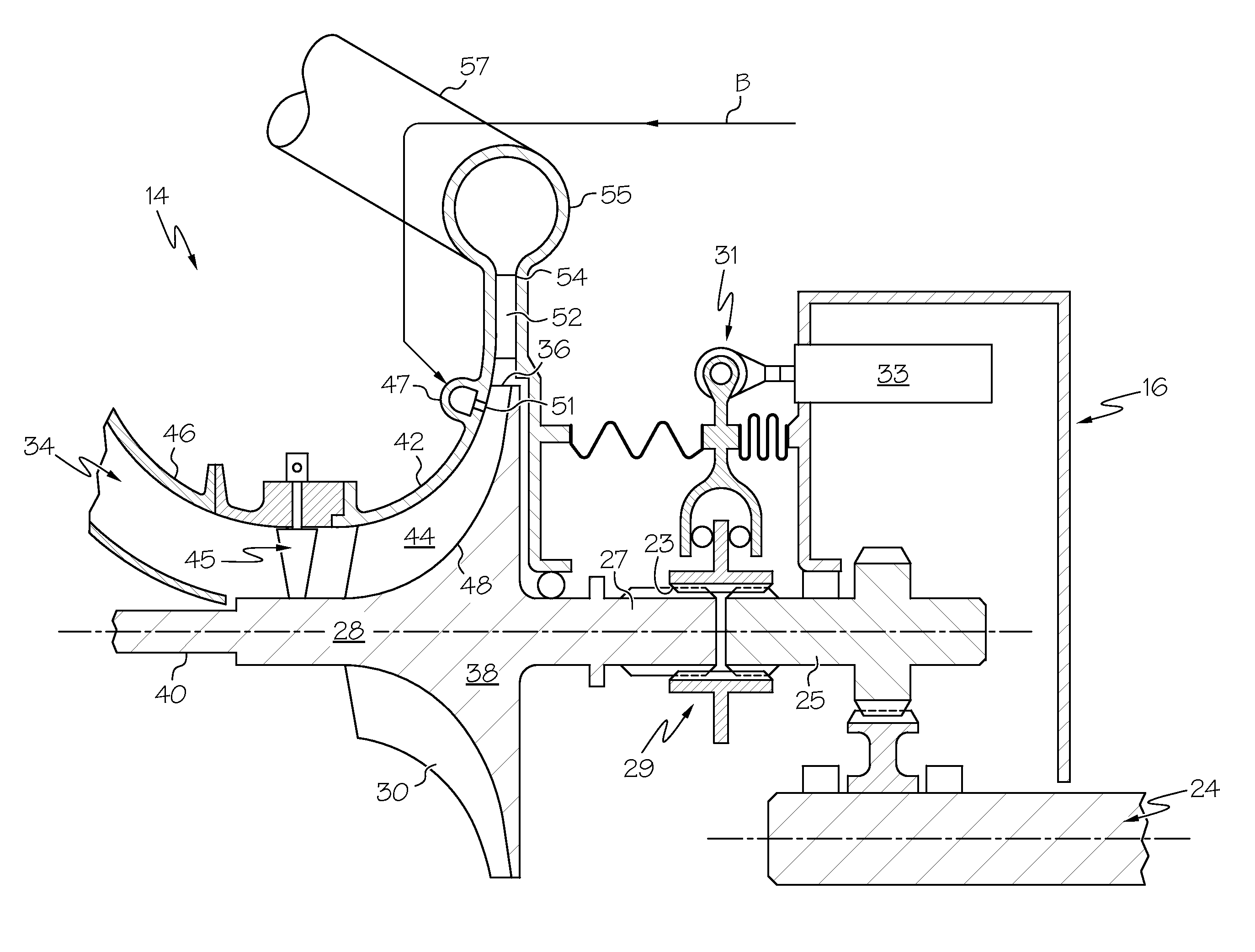
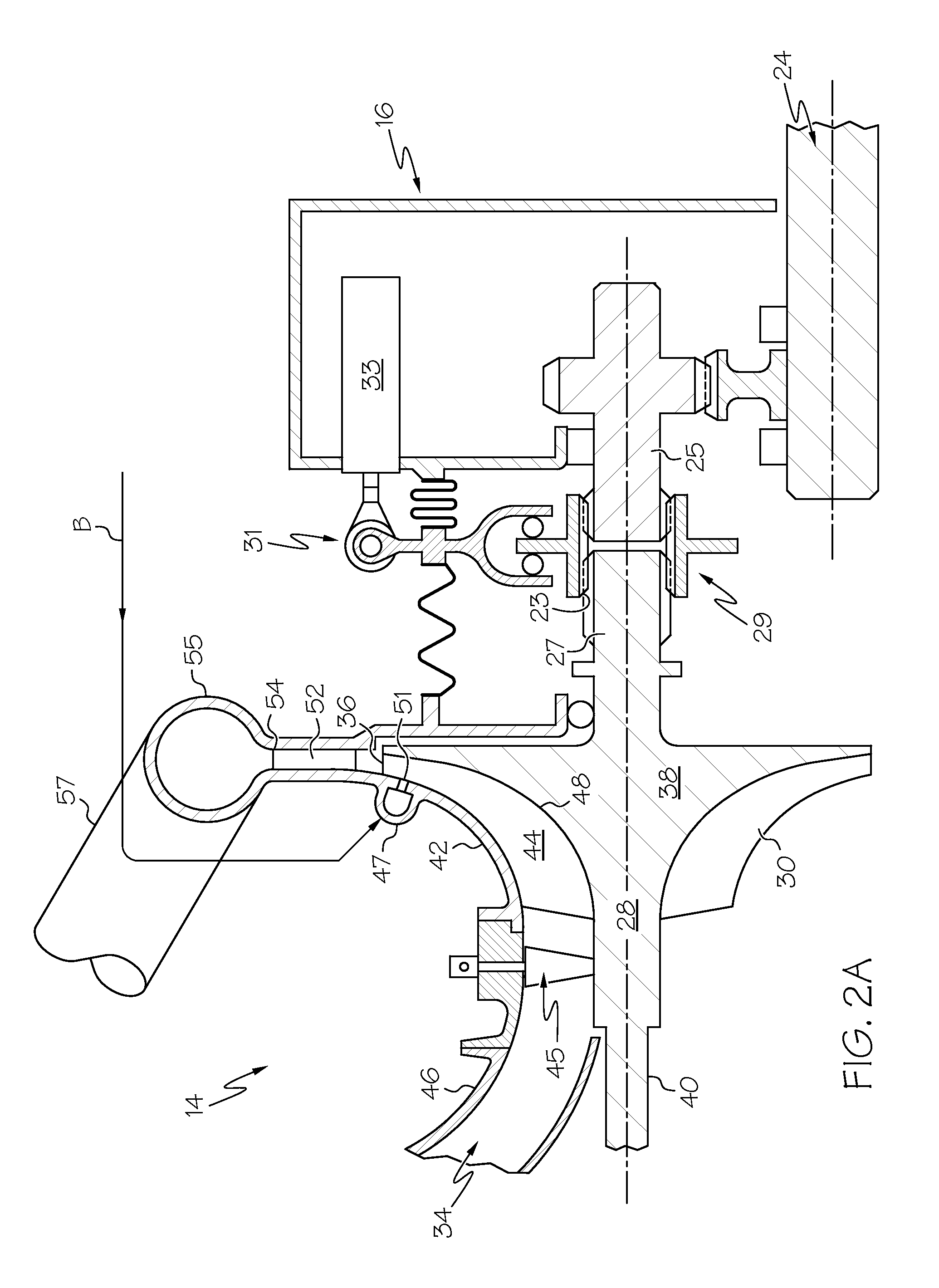
[0036]Referring now specifically to FIGS. 5A and 5B, in accordance with an alternative embodiment and as noted previously, the coupling 35 (FIG. 1) may comprise a friction clutch 129 and friction clutch actuator 131 which operate in a conventional manner, and therefore will not be described in detail. While a gearbox-driven compressor is illustrated in FIGS. 5A and 5B, it is to be understood that the load compressor may alternatively be directly driven by output shaft 24 as previously described. The pre-spinning and mechanically engaging steps (200 and 250) to engage the load compressor to the operating APU engine are generally the same as previously described, with the exceptions as noted below. Pre-spinning the impeller of the load compressor to a preset percentage of the rotational speed setpoint with a portion of the compressor discharge bleed air B (step 200) according to exemplary embodiments reduces the wear, and increases clutch life and overall reliability of the otherwise failure-prone friction clutch. The relative speed differential between the gearbox output shaft 25 and the LC drive shaft 27 is reduced (as opposed to eliminated when using the clutchless coupling member) by pre-spinning the LC impeller prior to friction clutch engagement. When pre-spinning the impeller and using a friction clutch, the rotational speed setpoint for the pre-spun impeller may be from about 50% to about 90% of the rotational speed of the output shaft 24 or 25 before engagement of the friction clutch. The pre-spinning step also minimizes the amount of bleed air usage in situations where the gas generator compressor has insufficient surge margin to accommodate the relatively large bleed flow required to pre-spin the impeller to the rotational speed setpoint.
[0037]Friction clutches without the pre-spinning step are failure prone when used to engage and disengage a load compressor from an operating APU because, while sufficient pressure is maintained by the pressure plate carrier assembly 142 to prevent slippage at steady state conditions, very high slip rates occur during transient clutch engagement, especially during initial contact between the friction material (FM) and the pressure plates. The friction clutch undergoes transient slip between the driving pressure plates attached to the gearbox output shaft 25 and the driven clutch plate attached to the LC impeller. The LC impeller can accelerate quickly from zero speed to 100% gearbox output shaft speed in a few seconds, resulting in high temperature rise and high wear of the friction material. The transient loading can also result in high inertial forces and vibr

Problems solved by technology

Continued operation of the load compressor when pneumatic power is not needed (but the APU is still operating, albeit in “generator-only mode” to provide electrical power) results in a parasitic loss of fuel as well as undesirable air emissions.
Unfortunately, friction clutches that have been used to engage the load compressor with the operating APU engine and disengage the load compressor therefrom tend to be heavy and have less than ideal reliability in APUs due to high rotational sp

Method used


Image

  • AUXILIARY POWER UNITS (APUs) AND METHODS AND SYSTEMS FOR ACTIVATION AND DEACTIVATION OF A LOAD COMPRESSOR THEREIN
  • AUXILIARY POWER UNITS (APUs) AND METHODS AND SYSTEMS FOR ACTIVATION AND DEACTIVATION OF A LOAD COMPRESSOR THEREIN
  • AUXILIARY POWER UNITS (APUs) AND METHODS AND SYSTEMS FOR ACTIVATION AND DEACTIVATION OF A LOAD COMPRESSOR THEREIN

Examples


Example

[0018]The following detailed description is merely exemplary in nature and is not intended to limit the invention or the application and uses of the invention. As used herein, the word “exemplary” means “serving as an example, instance, or illustration.” Thus, any embodiment described herein as “exemplary” is not necessarily to be construed as preferred or advantageous over other embodiments. All of the embodiments described herein are exemplary embodiments provided to enable persons skilled in the art to make or use the invention and not to limit the scope of the invention which is defined by the claims. Furthermore, there is no intention to be bound by any expressed or implied theory presented in the preceding technical field, background, brief summary, or the following detailed description.

[0019]Various embodiments are directed to auxiliary power units (APUs) and systems and methods for activation and deactivation of a load compressor therein. The load compressor is adapted to be...


PUM


Abstract

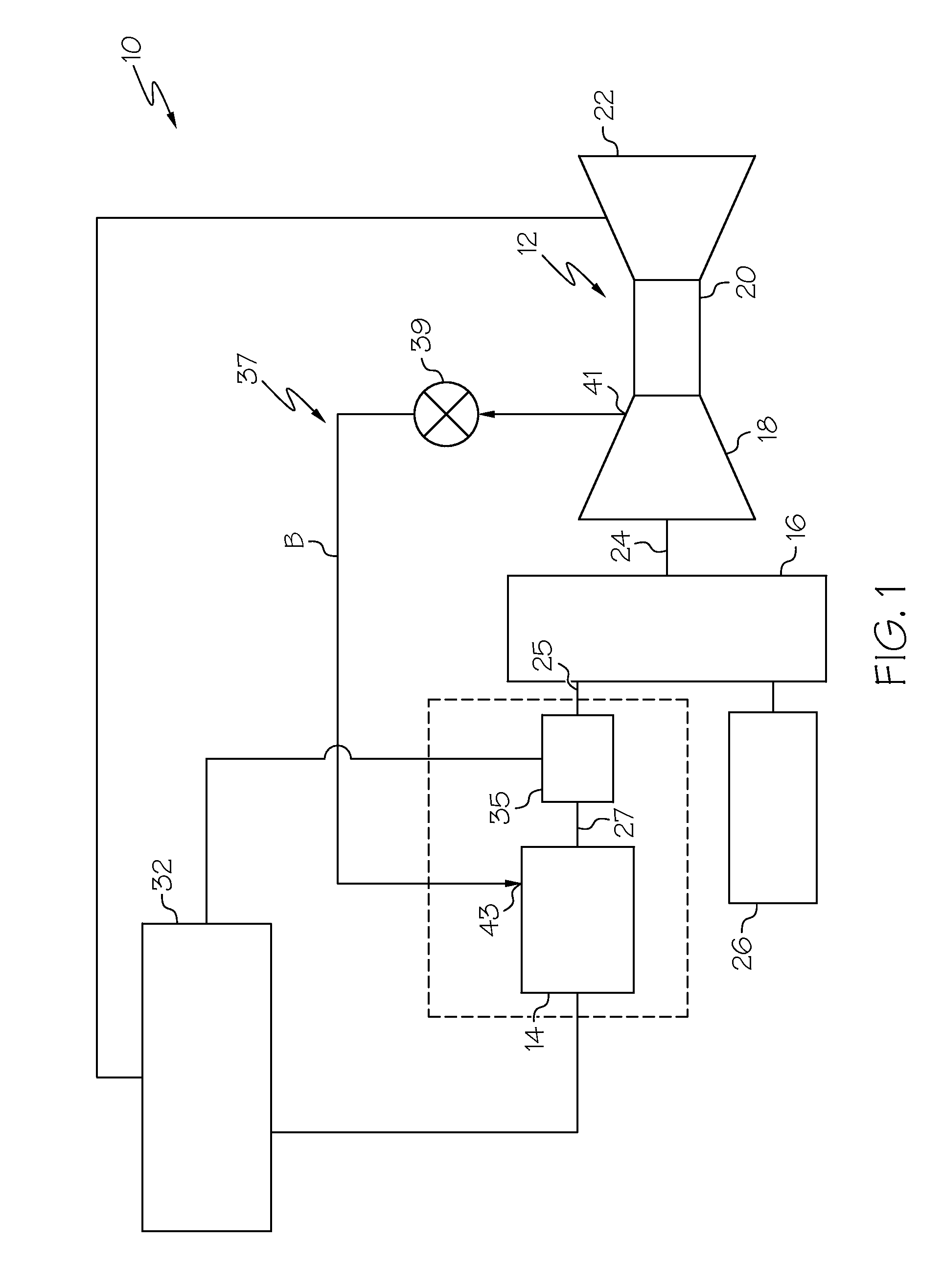
Auxiliary power units and methods and systems for activation and deactivation of a load compressor therein are provided. Auxiliary power unit includes the load compressor having an impeller, APU engine, coupling member, pre-spinning means, and APU controller. APU engine is adapted to be mechanically engaged to load compressor to drive load compressor to provide pneumatic power and to be disengaged when the need for pneumatic power ceases. Coupling member couples load compressor and APU engine and is configured to be controllably moved between an engaged position in which the APU engine is mechanically engaged with the load compressor, and a disengaged position, in which the APU engine is disengaged from the load compressor. APU controller is operably coupled to load compressor, APU engine, coupling member, and pre-spinning means and adapted to receive and be responsive to rotational speed signals for controlling movement of coupling member between engaged and disengaged positions.

Description

TECHNICAL FIELD[0001]The present invention generally relates to auxiliary power units (“APU”s), and more particularly relates to methods and systems for activation and deactivation of a load compressor therein.BACKGROUND[0002]An operating aircraft auxiliary power unit (APU) provides energy for functions other than propulsion. An APU generally consists of a gas turbine engine (hereinafter referred to as an “APU engine), a generator, and a load compressor (LC). Before the main propulsion engines are started, the APU engine is started, generally by a battery or hydraulic accumulator and fuel. The operating APU provides auxiliary electrical power and pneumatic power to the aircraft while the main propulsion engines are shut down, such as during aircraft ground operations and provides backup electrical and pneumatic power for in-flight operations. The operating APU supplies the electrical power via the generator which is driven by the operating APU engine. The activated load compressor i...

Claims


Application Information

Patent Timeline
IPC IPC(8): F04D25/02
CPCF04D25/02B64D41/00F04D25/022F04D17/10F05D2220/50F01D15/08F04D27/0292F02C6/08F02C9/18
Inventor JAN, DAVID K.ZOLLARS, CHRISTOPHER
Owner HONEYWELL INT INC
Why Eureka
Try Eureka