Inductive load control device

A load control and inductive technology, applied in the control system, DC motor speed/torque control, electrical components, etc., can solve the problems of difficult cost control, excessive instantaneous current increase, inability to maintain long-term operation and component life, etc., to achieve Avoid the influence of switching sparks, increase the life and reliability of the effect

Active Publication Date: 2007-02-28
HIWIN MIKROSYST
View PDF1 Cites 6 Cited by
  • Summary
  • Abstract
  • Description
  • Claims
  • Application Information

AI Technical Summary

Problems solved by technology

[0007] First, the above-mentioned control method needs to provide the first relay 11 or the preset excitation voltage of the second relay 12 before providing a control voltage on the gate terminal of the first field effect crystal 14, so the entire control circuit will be too much. Complicated and increased production costs;
[0008] Its two, the gate end of this first field effect crystal 14 must have a control voltage to generate, but this control voltage often can first drive generation because the circuit is subjected to abnormal influence, if the excitation voltage of the first relay 11 or the second relay 12 drives again subsequently , it will cause the first normally open contact 133 or the second normally open contact 133a of the first relay 11 or the second relay 12 to be damaged due to the excessive increase of the instantaneous current driving the first inductive load 10;
[0009] Third, as shown in Figure 1, the user must set up a control system to ensure that the first relay 11 and the second relay 12 act first before driving the first field-effect crystal 14, and the aforementioned actions need to be delayed by components. Achieved (difficult to control);
[0010] Fourth, when two groups of first relays 11 and second relays 12 act at the same time, the current flowing into the load will flow through the first relay switch 13 and the second relay switch 13a of each first relay 11 and second relay 12. Sparks at the contacts cause damage to the contacts
[0011] It can be seen from the above products that in the past, when using inductive load control systems, it was impossible to maintain stable operation and component life for a long time; in view of the above defects, in today's pursuit of ideals, practicability and progress, we are sincerely looking forward to striving for the goal of improvement
[0012] In view of this, the inventor of this invention has developed a new control device for inductive load control after careful consideration and years of experience in various inductive load control systems and related technologies to achieve this goal. Invent the effect of avoiding the spark of switching action; effectively improve the common problems in the past, such as the reduction of life span and the increase of cost that are difficult to control

Method used


Image

  • Inductive load control device
  • Inductive load control device
  • Inductive load control device

Examples


no. 1 example

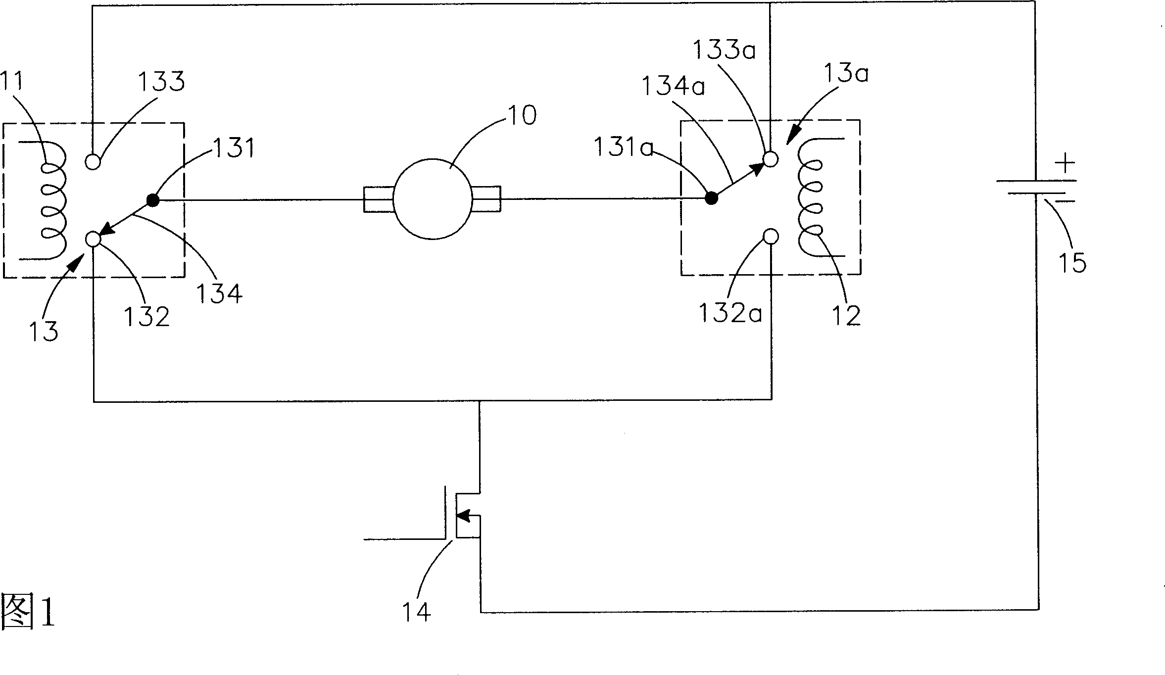
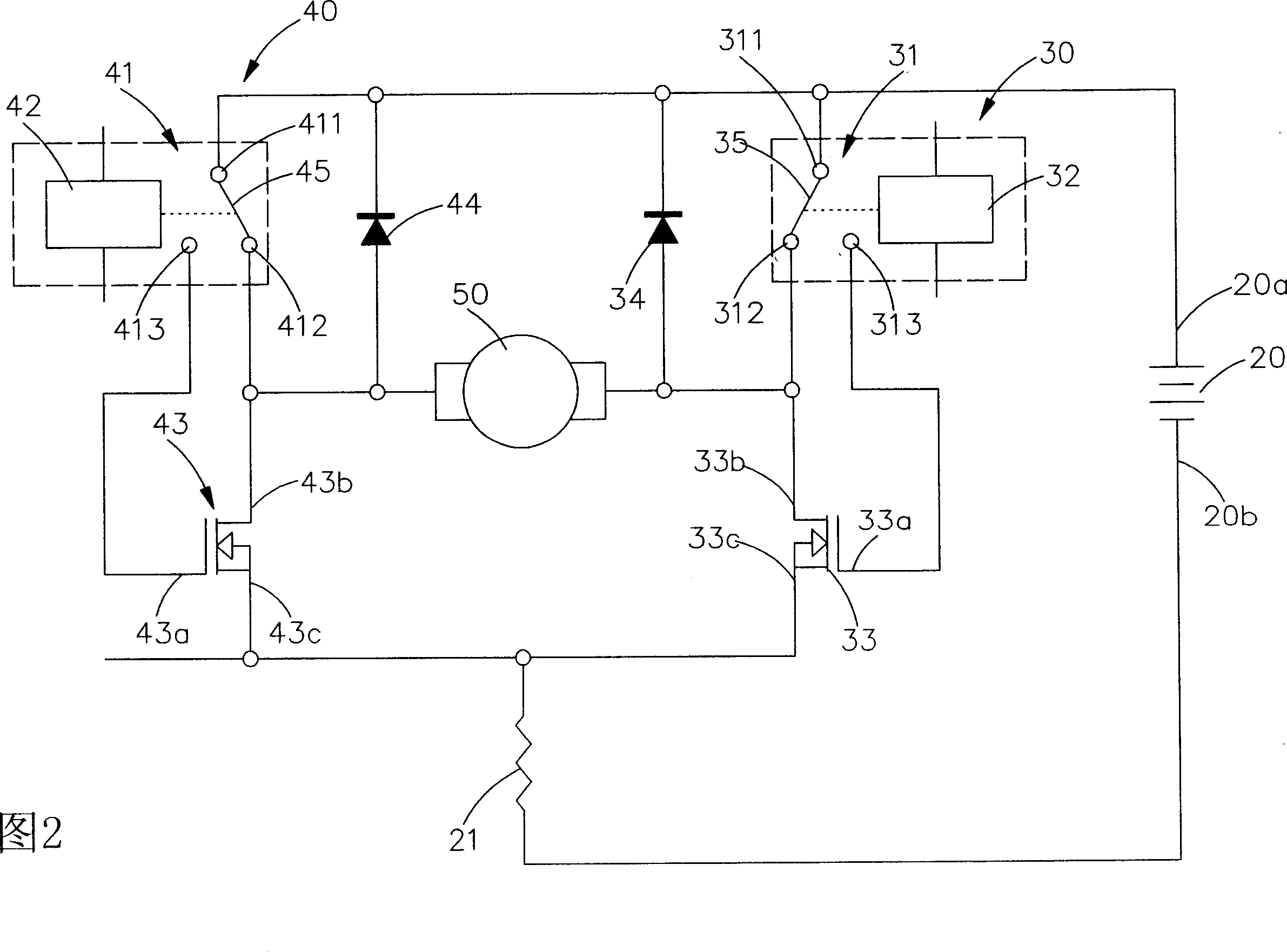
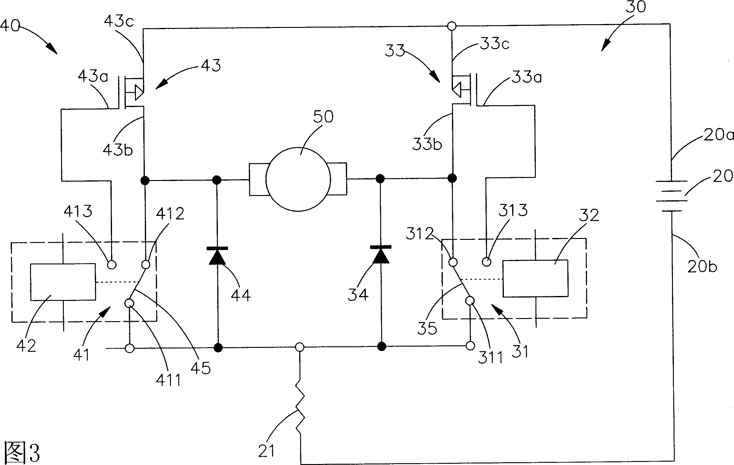
[0061] The first embodiment of the inductive load control device of the present invention uses an N-type field effect crystal (N-MOSFET). The schematic diagram is shown in FIG. Control group 40 and a second inductive load 50 (see FIG. 2); wherein:

[0062] The power supply 20, assembled in a circuit, has a positive terminal 20a and a negative terminal 20b;

[0063] The resistor 21 is used to detect the current, and it is connected in series with the negative terminal 20b of the power supply 20;

[0064] The first control group 30 is connected in series between the positive terminal 20a of the power supply 20 and the resistor 21. The first control group 30 includes a third relay switch 31, a third relay 32, a second field Effect crystal 33 and a first diode 34 combined, the second field effect crystal 33 is an N-type field effect crystal, the third relay switch 31 cooperates with a first reed 35 with a third common contact 311 A third normally closed contact 312 and a third n...


PUM


Abstract

The invention relates to an inductive load controller, used to control common inductive load (as motor, direct-current motor). Wherein, it uses the theory that the field-effect crystal (MOSFET) has no switch contactor, to avid switch splash, and uses the open contactor between the grids of two field-effect transistor and two relay switches. The invention can confirm first completing the contact of relay switch and then completing the contact of field-effect transistor, when the relay switch drives the inductive load, therefore, the contactor of relay switch will not have splash, to prolong the service life and reliability of control contactor of relay switch.

Description

technical field [0001] The present invention provides a brand-new inductive load control device, which is applied to control general inductive loads (such as: motors, DC motors, etc.), and can avoid the influence of switching sparks, and can increase the number of relay switch control contacts life and reliability. Background technique [0002] According to, due to the continuous development and improvement of inductive load systems, various control inductive load technologies and their products have become very important parts of many precision machines, and various inductive load mechanism products have widely entered human life. In , processing plants and high-tech equipment, although the development of inductive load technology is very rapid, consumers still need continuous improvement of technology, so there are also many control systems for inductive loads (inductive loads such as: motors, DC motors, etc.), but today's inductive load technology still has many problems...

Claims


Application Information

Patent Timeline
IPC IPC(8): H02P7/00
Inventor 郑其原
Owner HIWIN MIKROSYST
Why Eureka
Try Eureka