Process for making a turbulator by additive manufacturing

a technology of additive manufacturing and turbulence, which is applied in the direction of turbines, manufacturing tools, light and heating equipment, etc., can solve the problems of increasing both cost and fabrication time of components, high turbulence, and reducing efficiency

Active Publication Date: 2016-12-06
GE INFRASTRUCTURE TECH INT LLC
View PDF19 Cites 5 Cited by
  • Summary
  • Abstract
  • Description
  • Claims
  • Application Information

AI Technical Summary

Problems solved by technology

The disruption in the flow creates shear layers and high turbulence to enhance heat transfer on the exterior surface and increase convective cooling of the component.
Forming the plurality of turbulators may require an extended period of time, which decreases efficiency and increases both cost and fabrication time for the component.

Method used


Image

  • Process for making a turbulator by additive manufacturing
  • Process for making a turbulator by additive manufacturing
  • Process for making a turbulator by additive manufacturing

Examples


example

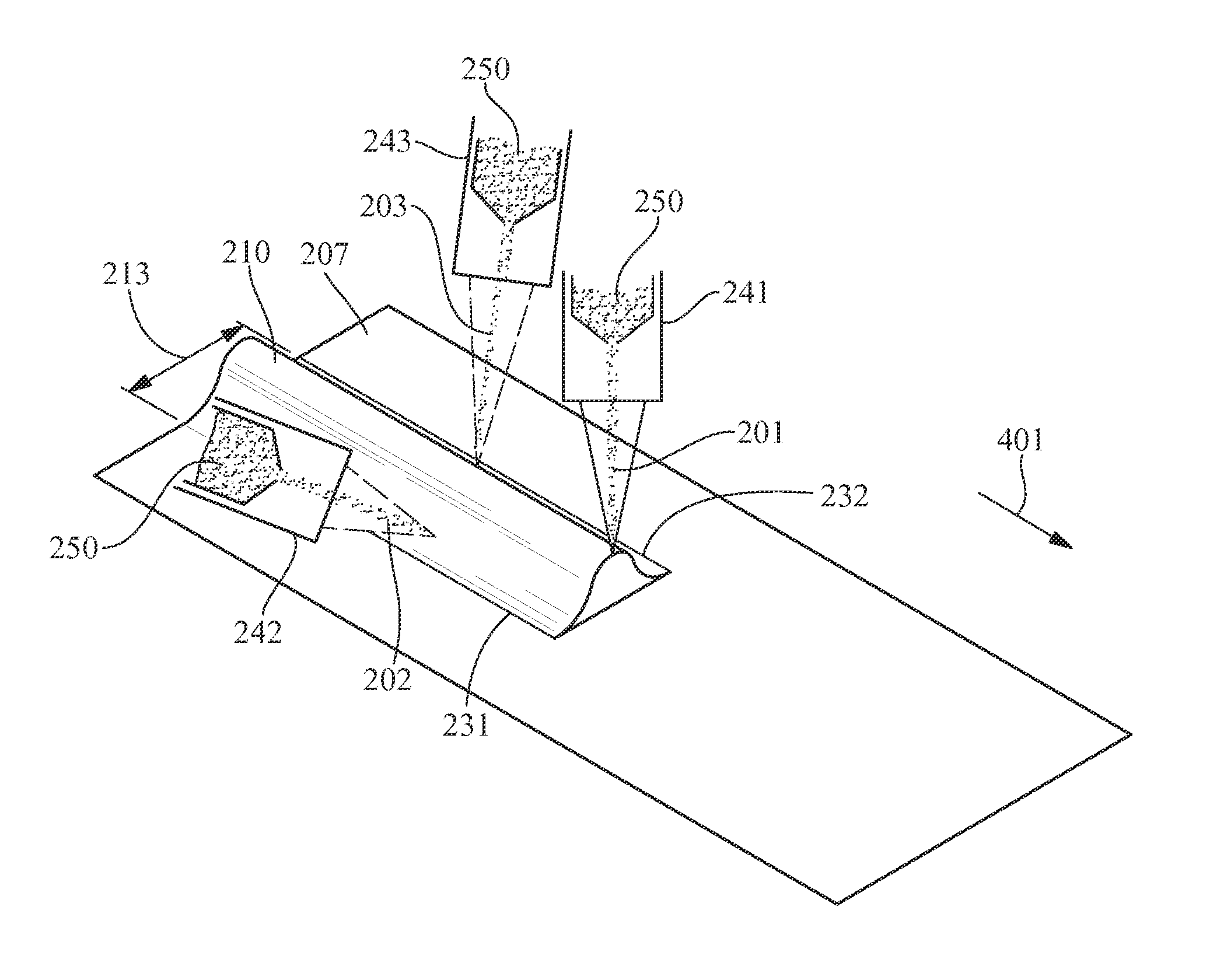
[0031]In an example, a first laser energy with a power of 700 w is directed towards an external surface of a combustion liner to form a portion of the turbulator 210. The first laser energy is directed from the first fusion energy source 241 concurrently with the powder feeding 250 to deposit the powder material on the substrate 207 and position the turbulator material 205 (step 120) simultaneously with the directing of the fusion energy (step 130). Concurrently with the directing of the first laser energy, a second laser energy with a power of 300 w is directed toward the first side 231 of the turbulator 210, and a third laser energy with a power of 300 w is directed toward the second side 232 of the turbulator 210. The first laser energy, the second laser energy, and the third laser energy proceed in the direction of formation 401 at 35 ipm, with the second laser energy and the third laser energy trailing the first laser energy to form the first root portion 214 and the second roo...


PUM

PropertyMeasurementUnit
flame temperaturesaaaaaaaaaa
heightsaaaaaaaaaa
heightsaaaaaaaaaa

Abstract

A turbulator fabrication process and a fabricated article are provided. The turbulator fabrication process includes providing a system configured for directing a first fusion energy and a second fusion energy, positioning a turbulator material on a substrate, and directing the first fusion energy and the second fusion energy toward the turbulator material and the substrate. The directing of the first fusion energy and the second fusion energy modifies the turbulator material forming one or more turbulators on the substrate. The fabricated article includes a substrate and one or more turbulators formed on the substrate. Each of the one or more turbulators includes at least one root portion providing a concave transition between the substrate and the turbulator.

Description

FIELD OF THE INVENTION[0001]The present invention is directed to a fabrication process and a fabricated article. More specifically, the present invention is directed to a turbulator fabrication process and a fabricated article including turbulators.BACKGROUND OF THE INVENTION[0002]Many components, such as gas turbine combustors, are exposed to increased temperatures during operation. For example, combustion within a combustion chamber of a traditional gas turbine may produce flame temperatures exceeding 3,900° F. Often, the components include tolerance temperatures well below the increased temperatures experienced during operation. To maintain material temperatures below the tolerance temperature, cooling features may be incorporated into the component.[0003]One cooling feature includes providing continuous linear turbulators on an exterior surface of a component, such as a combustor liner. The continuous linear turbulators include protruding bodies placed in the flow path over the ...

Claims


Application Information

Patent Timeline
Patent Type & Authority Patents(United States)
IPC IPC(8): B23K26/00F23R3/00B23K26/32F23R3/44B23K26/06B23K10/00B23P15/00
CPCB23K26/0078B23K26/0081B23K26/0608B23K26/144B23K26/32B23K26/342B23P15/008F23R3/005F23R3/44B23K2201/001B23K2203/08F23R2900/00018F23R2900/03045Y10T29/49323B23K2103/16B23K26/354B23K26/3584B23K2101/001B23K2103/02B23K2103/08B23K2103/26B23K2103/52F23R3/002F23R3/16
Inventor LIN, DECHAOKOTTILINGAM, SRIKANTH CHANDRUDUCUI, YANBUCCI, DAVID VINCENTDIAO, XIAOXUE
Owner GE INFRASTRUCTURE TECH INT LLC
Why Eureka
Try Eureka