Electric wire holding device and wire harness

a technology of holding device and electric wire, which is applied in the direction of cable termination, semiconductor/solid-state device details, hermetically sealed casings, etc., can solve the problems of electric wire holder wobble in the shielding case, difficulty in mate the shielding case to the electric wire holder, etc., to facilitate the mate of the shielding case 22 and suppress the wobbling. , the effect of suppressing the wobbling

Active Publication Date: 2016-12-06
HITACHI METALS LTD
View PDF18 Cites 0 Cited by
  • Summary
  • Abstract
  • Description
  • Claims
  • Application Information

AI Technical Summary

Benefits of technology

[0009]Accordingly, it is an object of the present invention to provide an electric wire holding device and a wire harness, capable of tolerating a dimensional error to facilitate the mating of a cylindrical member to an electric wire holding member and suppress the wobbling of the electric wire holding member received in the cylindrical member.(1) According to one embodiment of the invention, an electric wire holding device comprises:
[0025]The electric wire holding device and the wire harness according to the present invention allow for tolerating a dimensional error to facilitate the mating of the cylindrical member to the electric wire holding member and suppress the wobbling of the electric wire holding member received in the cylindrical member.

Problems solved by technology

The electric wire holding device disclosed by JP Patent No. 3819229 has had a dimensional error of its electric wire holder or shielding case which has caused the electric wire holder to be greater in a dimension in a direction at right angles to the mating direction than the shielding case, thus making it difficult to mate the shielding case to the electric wire holder.
Also, when the space between the outer surface of the electric wire holder and the inner surface of the shielding case has been large, the electric wire holder has wobbled in the shielding case.

Method used


Image

  • Electric wire holding device and wire harness
  • Electric wire holding device and wire harness
  • Electric wire holding device and wire harness

Examples


first embodiment

[0036]Configurations of an electric wire holding device 2 and a wire harness 11 in a first embodiment of the present invention are described with reference to FIGS. 1 to 4.

[0037]This wire harness is mounted on a vehicle, and used to provide driving current for vehicle traction, for example.

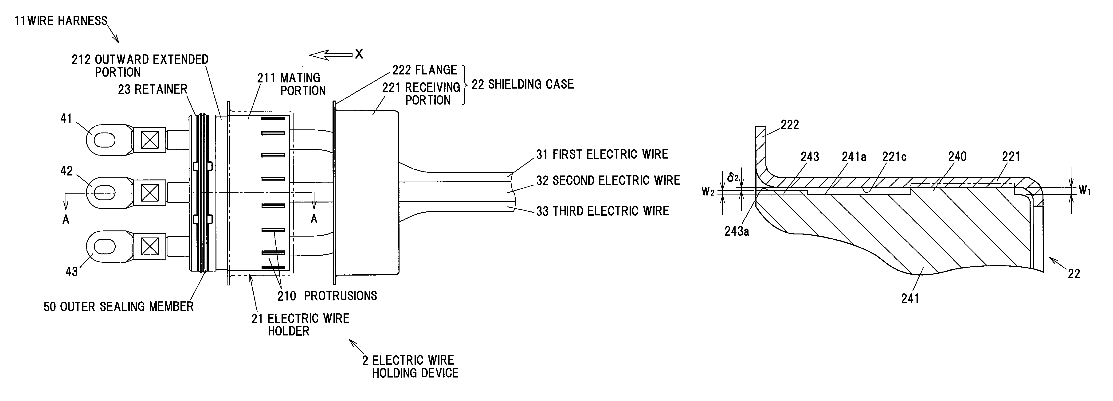
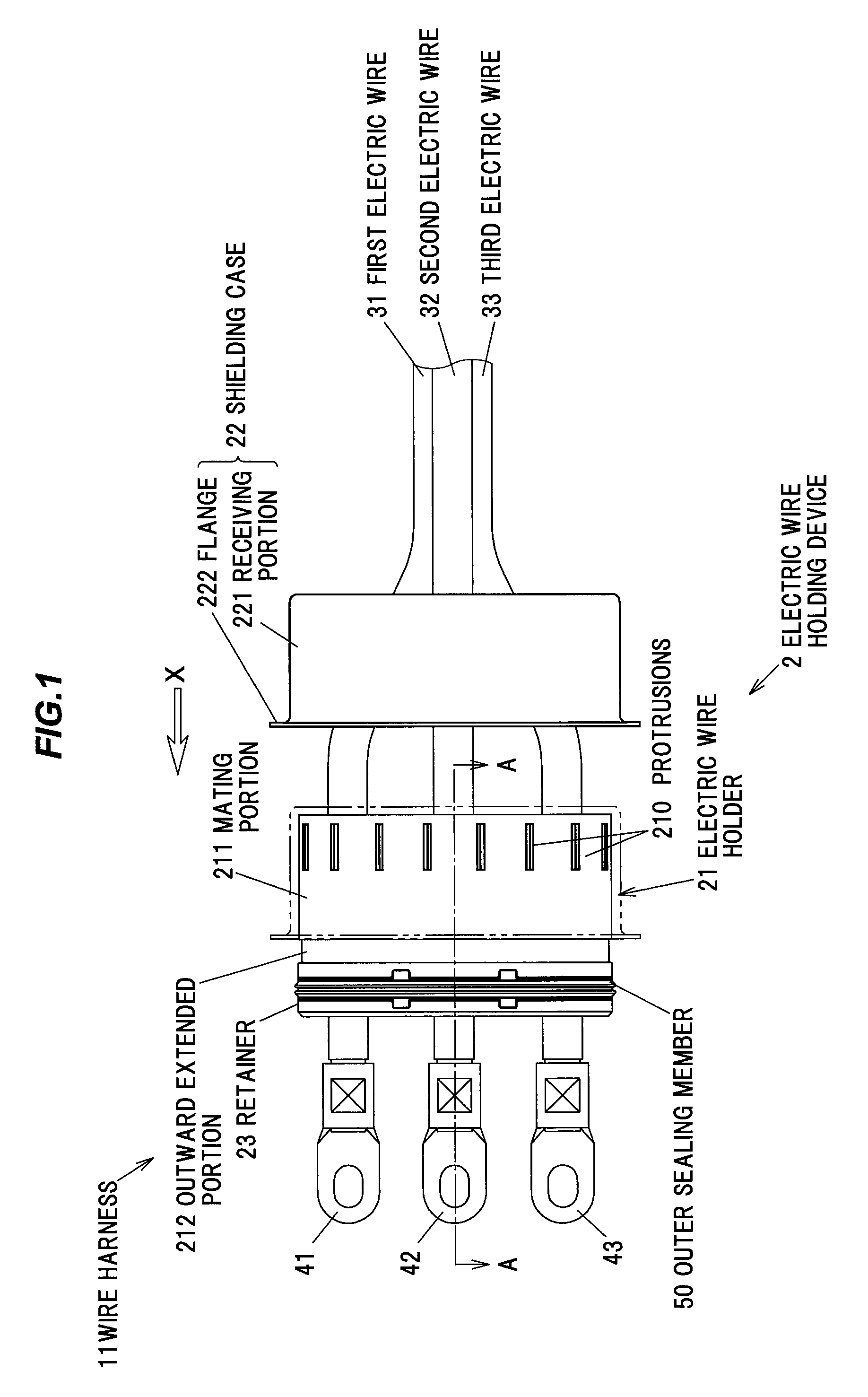
[0038]FIG. 1 is a configuration diagram showing one configuration example of the electric wire holding device 2 and the wire harness 11 with that electric wire holding device 2 in the first embodiment of the present invention. Note that, for description, FIG. 1 shows the electric wire holding device 2 with its shielding case 22 not mated to its electric wire holder 21, but with its shielding case 22 indicated by alternate long and two short dashes line mated to its electric wire holder 21.

[0039]The wire harness 11 includes first to third electric wires 31 to 33, an electric wire holder 21 made of a resin serving as an electric wire holding member to hold the first to third electric wires 31 to 33,...

second embodiment

[0072]Next, a second embodiment of the present invention is described with reference to FIGS. 5 and 6.

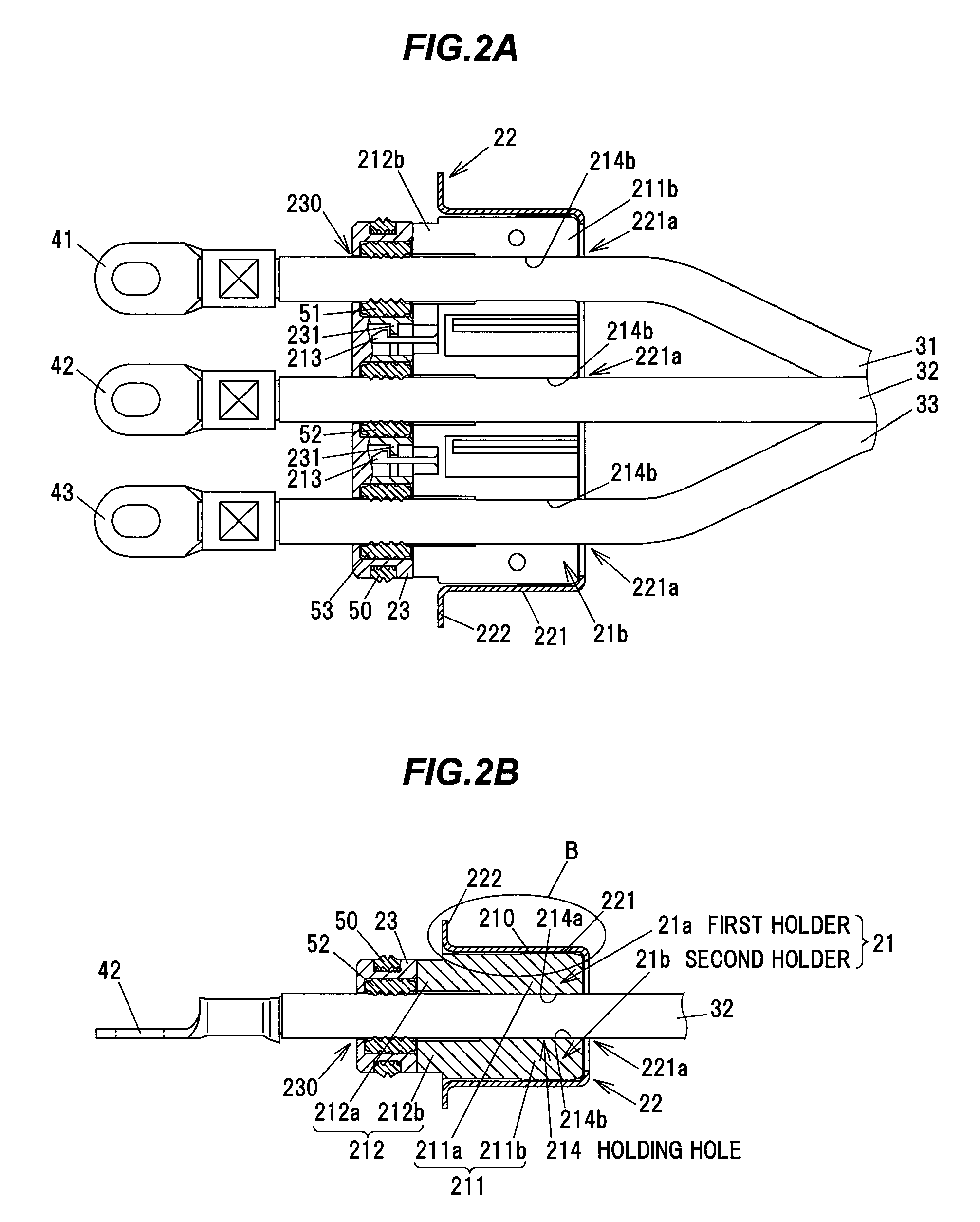
[0073]FIG. 5 is a configuration diagram showing one configuration example of an electric wire holding device 20 and a wire harness 12 with that electric wire holding device 20 in a second embodiment of the present invention. FIG. 6A is a cross sectional view along D-D line in FIG. 5 showing the wire harness 12 in the second embodiment, and FIG. 6B is an enlarged view showing portion indicated by E in FIG. 6A. Note that FIG. 5 shows the wire harness 12 with its shielding case 22 indicated by alternate long and two short dashes line mated to its electric wire holder 24. In FIG. 6B, an undeformed shape of protrusions 240 is indicated by alternate long and two short dashes line.

[0074]In FIGS. 5 and 6, constituent elements having analogous functions to those described in the first embodiment are given common numerals or characters, and duplicated descriptions thereof are omitted.

[0075]In...


PUM


Abstract

An electric wire holding device is composed of an electric wire holding member made of a resin to hold an electric wire, a cylindrical member made of an electrically conductive metal, including an inner surface to be mated around and receive at least a mating portion of the electric wire holding member, and a plurality of protrusions formed around an outer circumference of the at least mating portion of the electric wire holding member for the cylindrical member to be mated therearound. The plurality of protrusions are brought into contact with the inner surface of the cylindrical member.

Description

[0001]The present application is based on Japanese patent application No. 2014-076250 filed on Apr. 2, 2014, the entire contents of which are incorporated herein by reference.BACKGROUND OF THE INVENTION[0002]1. Field of the Invention[0003]This invention relates to an electric wire holding device to hold an electric wire, and a wire harness including that electric wire holding device and that electric wire.[0004]2. Description of the Related Art[0005]A conventional electric wire holding device is known that is equipped with a metallic shielding case (cylindrical member) and an electric wire holder (electric wire holding member) to be received in that shielding case to fix relative locations of a plurality of electric wires in that shielding case (Refer to e.g. JP Patent No. 3819229).[0006]The electric wire holding device disclosed by JP Patent No. 3819229 is equipped with the shielding case to be attached to a unit housing having a plurality of inserting portions therethrough for a p...

Claims


Application Information

Patent Timeline
Patent Type & Authority Patents(United States)
IPC IPC(8): H01R9/05H01J15/00H01J5/00H02G15/013H02G15/04H05K5/06H01R13/40H01R13/52H01L23/055H01L23/045
CPCH02G15/046H02G15/013
Inventor IMAHORI, MASAAKI
Owner HITACHI METALS LTD
Why Eureka
Try Eureka